
Liquid-cooling device of high-power self-coupling transformation rectifier for civil aircraft

An autotransformer, cooling device technology, applied in cooling/ventilation/heating transformation, electrical components, electrical equipment structural parts, etc., can solve the problem of increasing the volume occupied by external liquid cooling pipes, increasing the volume of internal liquid cooling pipes, Increase the difficulty of design and processing to achieve the effect of simple structure, improved power-to-weight ratio, and reduced size

Active Publication Date: 2017-09-29
BEIJING AERONAUTIC SCI & TECH RES INST OF COMAC +1
View PDF6 Cites 1 Cited by
  • Summary
  • Abstract
  • Description
  • Claims
  • Application Information

AI Technical Summary

Problems solved by technology

There are some deficiencies in the heat dissipation device: no design and calculation of hot spots will lead to an increase in the volume of the internal liquid cooling pipe, which will not be able to effectively dissipate heat from the hot spots, will increase the volume of the radiator, and then increase the volume and weight of the device; application In the field of civil aircraft, the different positions of the liquid inlet and outlet in the device will increase the volume occupied by the external liquid cooling pipe; the microchannel design increases the difficulty of design and processing

Method used


Image

  • Liquid-cooling device of high-power self-coupling transformation rectifier for civil aircraft
  • Liquid-cooling device of high-power self-coupling transformation rectifier for civil aircraft
  • Liquid-cooling device of high-power self-coupling transformation rectifier for civil aircraft

Examples


Embodiment Construction

[0020] Specific embodiments of the present invention will be described in detail below in conjunction with specific drawings. It should be noted that the technical features or combinations of technical features described in the following embodiments should not be regarded as isolated, and they can be combined with each other to achieve better technical effects. In the drawings of the following embodiments, the same reference numerals appearing in each drawing represent the same features or components, which can be applied in different embodiments.

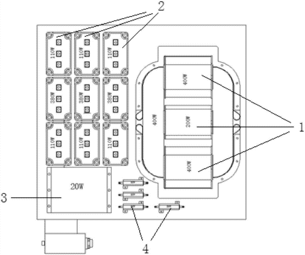
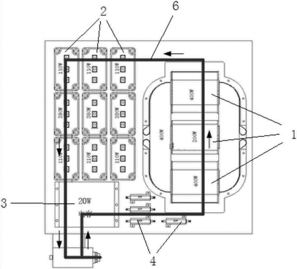
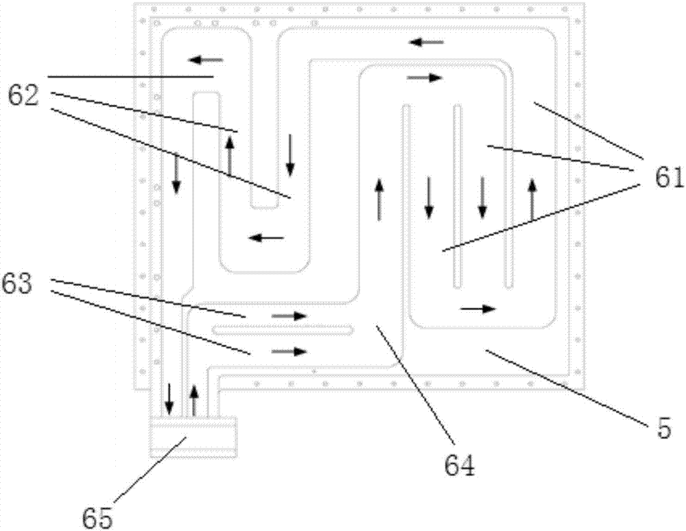
[0021] like Figure 1-3 As shown, the embodiment of the present invention is a liquid-cooled cooling device for a high-power autotransformer rectifier of a civil aircraft, including a liquid-cooled backplane 5 and a liquid-cooled flow channel 6; A transformer 1, a rectifier bridge 2, a capacitor 3, and a resistor 4; the heating component is arranged on one side of the liquid-cooled backplane 5; the liquid-cooled flow channel 6 is ...


PUM


Abstract

The invention relates to the technical field of cooling of an aircraft transformation rectifier, and provides a liquid-cooling device of a high-power self-coupling transformation rectifier for a civil aircraft. The liquid-cooling device comprises a liquid-cooling back plate and a liquid-cooling runner, wherein a heat generation part of the self-coupling transformation rectifier comprises a self-coupling transformer, a rectification bridge, a capacitor and a resistor, the power generation part is arranged on a surface of the liquid-cooling back plate, the liquid-cooling runner is arranged on the other surface, opposite to the heat generation part, of the liquid-cooling back plate and comprises a transformer segment, a rectification bridge segment, a capacitor segment and a resistor segment which are sequentially connected, and a liquid inlet and a liquid outlet of the liquid-cooling runner are integrated to jointly form a liquid-cooling interface. The liquid-cooling device has the beneficial effects of high heat dissipation efficiency, the weight of the whole self-coupling transformation rectifier is reduced, the noise influence is eliminated, the power-to-weight ratio is improved, and the economy of a large-size civil aircraft is favorably improved; an input-output pipe orifice is integrated to a liquid-cooling interface, and the integrated installation of the self-coupling transformation rectifier and other liquid-cooling equipment is more favorably integrated; and the liquid-cooling device is simple in structure and has wide application prospect.

Description

technical field [0001] The invention relates to the technical field of cooling of aircraft transformer rectifiers, in particular to a liquid cooling device for high-power autotransformer rectifiers of civil aircraft. Background technique [0002] With the continuous development of multi-power technology, the power supply capacity and voltage level of large civil aircraft continue to increase. With the increasing number of electrical equipment on the aircraft, the capacity of the power conversion device that converts the primary power supply and supplies power to the load has increased significantly. , and the corresponding heat dissipation is also increasing. [0003] Traditional narrow-body civil aircraft power conversion devices have low power. For example, the C919 airliner has two power conversion devices, the transformer rectifier (TRU) and the static converter (INV). The power of the transformer rectifier is 9.8kW, and the heat dissipation is 1470W. The static convert...

Claims


Application Information

Patent Timeline
IPC IPC(8): H05K7/20
CPCH05K7/20927
Inventor 王春成何旭楠刘卫芳李澎
Owner BEIJING AERONAUTIC SCI & TECH RES INST OF COMAC
Learn More