Quick combined cycle steam turbine starting and warming system and method

A fast-start, combined cycle technology, applied in the field of gas-steam combined cycle systems, can solve problems such as low thermal efficiency and increase power generation costs, increase peak shaving capacity and power generation, eliminate clutch damage, and shorten cold start requirements. effect of time

Active Publication Date: 2017-10-03
SHANGHAI ELECTRIC POWER GENERATION EQUIPMENT CO LTD +2
View PDF5 Cites 5 Cited by
  • Summary
  • Abstract
  • Description
  • Claims
  • Application Information

AI Technical Summary

Problems solved by technology

Therefore, when starting up, either let the gas turbine run at low load for a long time and wait for the steam turbine to warm up, resulting in low thermal efficiency; or let the gas turbine load quickly to participate in peak-shaving operation. The steam generated by the boiler is not allowed to enter the steam turbine to do work, but is directly discharged to the condenser through the bypass, which inevitably produces a large energy loss and increases the cost of power generation

Method used


Image

  • Quick combined cycle steam turbine starting and warming system and method
  • Quick combined cycle steam turbine starting and warming system and method
  • Quick combined cycle steam turbine starting and warming system and method

Examples


Embodiment 1

[0053] Embodiment 1 of the present invention provides a method for quickly starting and warming up a combined cycle steam turbine. The method for quickly starting and warming up a combined cycle steam turbine in Embodiment 1 is suitable for cold start of a single-shaft combined cycle unit equipped with a clutch. The shaft combined cycle unit is equipped with a generator between the gas turbine and the steam turbine. One end of the generator shaft is connected to the rotor shaft of the gas turbine, and the other end of the generator shaft is connected to the rotor shaft of the steam turbine through a clutch. The gas turbine and the steam turbine share the same steam turbine barring device, and the steam turbine barring device is connected with the steam turbine. The capacity of the steam turbine barring device in the first embodiment should be capable of driving the steam turbine, the generator and the gas turbine to rotate at the same time.

[0054] The clutch in the first emb...

Embodiment 2

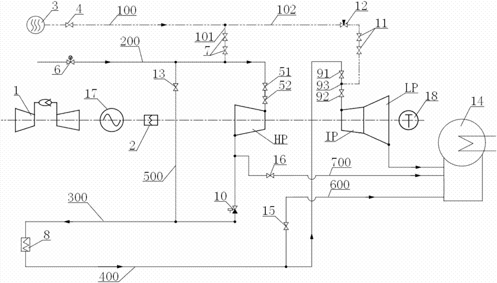
[0066] Such as figure 1 As shown, Embodiment 2 provides an embodiment of the combined cycle steam turbine quick start warm-up system of the present invention. The system for quickly starting and warming up a combined cycle steam turbine in Embodiment 2 can be used to realize the method for quickly starting and warming up a combined cycle steam turbine described in Embodiment 1.

[0067] Specifically, the combined cycle steam turbine quick-start warm-up system of the second embodiment includes a warm-up steam source 3 and a coaxially arranged gas turbine 1, a generator 17, a clutch 2 and a steam turbine, that is, one end of the generator 17 rotating shaft and The rotor shaft of the gas turbine 1 is connected, and the other end of the rotating shaft of the generator 17 is connected with the rotor shaft of the steam turbine through the clutch 2 . The steam turbine is connected with the steam turbine barring device 18, and the steam turbine can be dragged to rotate by the steam t...

Embodiment 3

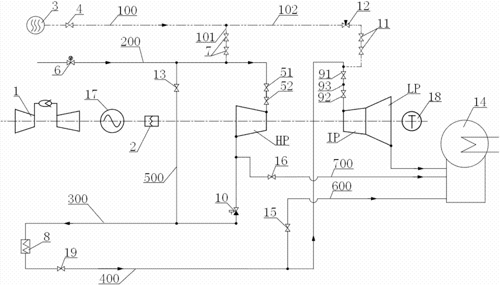
[0090] Such as figure 2 As shown, the third embodiment provides the second embodiment of the combined cycle steam turbine quick start warm-up system of the present invention. The third embodiment is basically the same as the second embodiment, and the similarities will not be repeated. The difference is that in the third embodiment, a gate valve 19 is provided on the medium-pressure steam inlet pipeline 400 upstream of the medium-pressure steam inlet valve group. , the warm-up steam delivery pipeline 100 communicates with the medium-pressure steam inlet pipeline 400 through the medium-pressure delivery pipeline 102 between the gate valve 19 and the medium-pressure steam inlet valve group. When the gate valve 19 is closed and the medium-pressure steam inlet valve group is opened, the warm-up steam in the warm-up steam delivery pipeline 100 can pass through the medium-pressure delivery pipeline 102 into the medium-pressure steam inlet pipeline 400, and then pass through the med...


PUM


Abstract

The invention relates to the technical field of fuel gas-steam combined cycle systems, in particular to a quick combined cycle steam turbine starting and warming system and method. The system comprises a gas turbine, a power generator, a self-synchronizing clutch, a steam turbine, a steam turbine turning gear and a warming steam source. The steam turbine comprises a high pressure cylinder, an intermediate pressure cylinder and a lower pressure cylinder. Warming steam conveying pipelines leading to the high pressure cylinder, the intermediate pressure cylinder and the lower pressure cylinder are connected to the warming steam source. The method comprises the steps that the rotating speed of the steam turbine is increased through the steam turbine turning gear so as to be higher than the rotating speed of the gas turbine; a main screw-type sliding part of the clutch is pried with a manual lever, so that the main screw-type sliding part slides towards the input end of the clutch till the phase positions of driving teeth and the phase positions of driven teeth of the clutch are aligned, and engagement of the clutch is achieved; warming steam is injected into the steam turbine, the steam turbine drives the gas turbine to rotate, and warming starts to be conducted; and when the temperature of an intermediate pressure rotor of the steam turbine reaches the preset temperature or the warming time reaches the preset time, warming is stopped. The cold start time can be shortened.

Description

technical field [0001] The invention relates to the technical field of gas-steam combined cycle systems, in particular to a system and method for quickly starting and warming up a combined cycle steam turbine. Background technique [0002] The steam turbine is one of the key power equipment in the construction of a power station, and it is an energy conversion device that converts thermal energy into mechanical energy and then into electrical energy. The high-temperature and high-pressure steam produced by the boiler converts the thermal energy and pressure potential energy into the mechanical energy of the steam turbine through the steam turbine, and drives the output shaft of the steam turbine rotor to do work. The mechanical energy is transmitted to the generator through the output shaft of the steam turbine rotor, thereby converting the mechanical energy into electrical energy . [0003] The gas-steam combined cycle system refers to using the gas turbine as a pre-turbin...

Claims


Application Information

Patent Timeline
Patent Type & Authority Applications(China)
IPC IPC(8): F01D25/10F01D19/00F01D25/34F01D17/10F01K13/02F02C6/00F16D11/16
CPCF01D17/10F01D19/00F01D25/10F01D25/34F01K13/02F02C6/00F16D11/16
Inventor 冯磊张立建阳虹何阿平虎煜
Owner SHANGHAI ELECTRIC POWER GENERATION EQUIPMENT CO LTD
Why Eureka
Try Eureka