
Auxiliary device for deploying wireless network, portable terminal and wireless network deployment method

An auxiliary device and wireless network technology, applied in the field of communication, can solve the problems of unstable information transmission path, frequent replacement, low network transmission performance, etc., and achieve the effect of saving network deployment cycle and workload.

Inactive Publication Date: 2017-10-03
FUJITSU LTD
View PDF5 Cites 2 Cited by
  • Summary
  • Abstract
  • Description
  • Claims
  • Application Information

AI Technical Summary

Problems solved by technology

Due to the invisibility of wireless electromagnetic waves, it is impossible for network deployment personnel to obtain real-time transmission performance of the deployed network in the current environment while deploying network nodes
In addition, while deploying the network, the construction personnel generally do not have a wealth of wireless communication knowledge. They only deploy the wireless multi-hop network based on simple construction experience. Often after the network deployment is completed, the network connectivity is not high, and the network The transmission performance is low, the information transmission path is unstable and frequently replaced, and the generation of isolated nodes prevents certain areas of information from being uploaded to the client, etc.

Method used


Image

  • Auxiliary device for deploying wireless network, portable terminal and wireless network deployment method
  • Auxiliary device for deploying wireless network, portable terminal and wireless network deployment method
  • Auxiliary device for deploying wireless network, portable terminal and wireless network deployment method

Examples


Embodiment 1

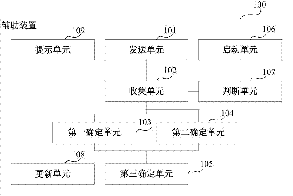
[0051] This embodiment provides an auxiliary device for wireless network deployment, figure 1 is a schematic diagram of the auxiliary device, such as figure 1 As shown, the auxiliary device 100 includes: a sending unit 101 , a collecting unit 102 , a first determining unit 103 , a second determining unit 104 , and a third determining unit 105 .

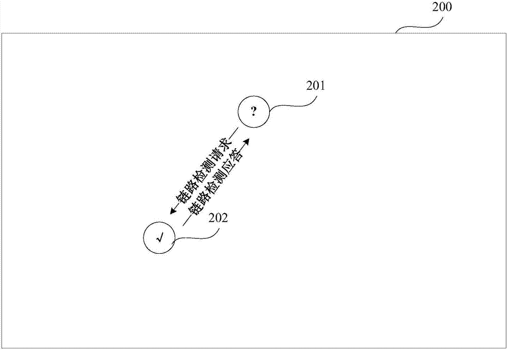
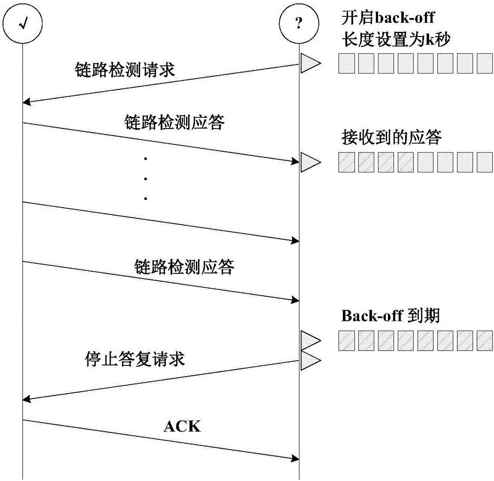
[0052] In this embodiment, the sending unit 101 is used for broadcasting a link detection request, and the collecting unit 102 is used for collecting link detection responses received within a predetermined time. The sending unit 101 and the collecting unit 102 can be realized by the wireless communication module as mentioned above.

[0053] In this embodiment, after the link detection response is collected by the sending unit 101 and the collection unit 102, the first determination unit 103 may use the node that sent the link detection response as the reference node of the device 100 to determine the For the target reference node a...

Embodiment 2

[0175] This embodiment also provides a portable terminal, Figure 14 is a schematic diagram of the portable terminal, such as Figure 14 As shown, the portable terminal 1400 includes the auxiliary device 100 described in Embodiment 1. Since the auxiliary device 100 has been described in detail in Embodiment 1, its content is incorporated here, and will not be repeated here.

[0176] Figure 15 It is a schematic block diagram of the system configuration of the portable terminal in this embodiment, as Figure 15 As shown, the portable terminal 1500 may include a central processing unit 1501 and a memory 1502; the memory 1502 is coupled to the central processing unit 1504. It is worth noting that this figure is exemplary; other types of structures may also be used in addition to or instead of this structure to implement telecommunications functions or other functions.

[0177] In one implementation, the functions of the auxiliary device 100 described in Embodiment 1 can be in...

Embodiment 3

[0189] The embodiment of the present invention also provides a wireless network deployment method. Since the problem-solving principle of this method is similar to that of the device in Embodiment 1, its specific implementation can refer to the implementation of the device in Embodiment 1, and the same content is not repeated. Repeat instructions.

[0190] Figure 16 is a flowchart of an embodiment of the method, such as Figure 16 As shown, the method includes:

[0191] Step 1601: broadcast link detection request;

[0192] Step 1602: Collect link detection responses received within a predetermined time;

[0193] Step 1603: Using the node sending the link detection response as a reference node, determine a target reference node and a non-target reference node of the device;

[0194] Step 1604: Determine the link connection status of the device relative to each reference node according to the received link detection response;

[0195] Step 1605: Determine the moving direct...


PUM


Abstract

The invention discloses an auxiliary device for deploying a wireless network, a portable terminal and a wireless network deployment method. The device comprises a sending unit which broadcasts link detection requests; a collection unit which is used for collecting link detection responses received in predetermined time; a first determining unit which is used for taking nodes sending the link detection responses as reference nodes and determining target reference nodes and non-target reference nodes of the device; a second determining unit which is used for determining a link connection state of the device relative to each reference node according to the link detection responses; and a third determining unit which is used for determining a moving direction and distance of the device according to the link connection state of the device relative to each reference node. A wireless network deployer is helped to carry out precise deployment on the nodes in a wireless network under a practical deployment scene.

Description

technical field [0001] The present invention relates to the field of communication technology, in particular to an auxiliary device for wireless network deployment, a portable terminal and a wireless network deployment method. Background technique [0002] Recently, the rapid development of wireless multi-hop network technology has made it easier for human society to obtain information, and the acquisition content has become more abundant. Typical wireless multi-hop networks include wireless sensor networks, wireless ad hoc networks and other forms. According to the different needs of human beings for information, wireless multi-hop networks are often deployed in different application environments to obtain corresponding data information. Such as the urban environment constructed of reinforced concrete, the open and unobstructed wild environment, the lush forest environment, and the vast grassland environment. For different environments, the network performance presented b...

Claims


Application Information

Patent Timeline
IPC IPC(8): H04W16/18
CPCH04W16/18H04W24/02H04W64/00H04W76/40H04B17/318H04L5/0055H04L43/0894H04W48/08
Inventor 奥琛李红春田军
Owner FUJITSU LTD
Learn More