
A method for wiring signal lines for modules

A wiring method and signal line technology, applied in the field of data communication, can solve the problems of reducing the surface layer wiring area, low cloth density, and increasing the surface layer density, so as to improve reliability and quality, reduce wiring area, improve The effect of surface cloth density

Active Publication Date: 2019-05-14
HISENSE & JONHON OPTICAL ELECTRICAL TECH CO LTD
View PDF9 Cites 0 Cited by
  • Summary
  • Abstract
  • Description
  • Claims
  • Application Information

AI Technical Summary

Problems solved by technology

[0003] The present invention provides a signal line wiring method for a module, which is used to solve the problem in the prior art that the surface wiring of the PCB board in the module and the device occupy a large area of ​​the module resulting in low cloth density, and is used to reduce the area of ​​the surface wiring. Increase the density of the surface layer to make the module miniaturized, and the signal line does not need to be drilled to change layers, improving the reliability and quality of signal transmission

Method used


Image

  • A method for wiring signal lines for modules
  • A method for wiring signal lines for modules
  • A method for wiring signal lines for modules

Examples


Embodiment Construction

[0015] In order to make the purpose, technical solutions and advantages of the embodiments of the present invention clearer, the technical solutions in the embodiments of the present invention will be clearly and completely described below in conjunction with the drawings in the embodiments of the present invention. Obviously, the described embodiments It is a part of embodiments of the present invention, but not all embodiments. Based on the embodiments of the present invention, all other embodiments obtained by persons of ordinary skill in the art without creative efforts fall within the protection scope of the present invention.

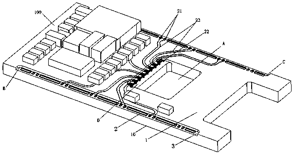
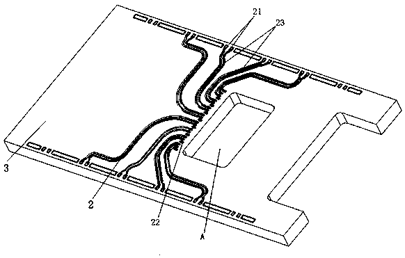
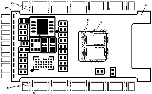
[0016] In order to avoid wiring on the surface layer or the first layer of the PCB board 10, reduce the density of the surface layer of the PCB board 10, and affect the miniaturization and high density of the module 100, such as Figure 1 to Figure 3 As shown, the present invention relates to a method for wiring signal lines for a module 100, whic...


PUM


Abstract

The invention relates to a signal line wiring method used for a module. The method comprises the following steps: (1) digging up a part of the whole part between the first layer and the upper surface of the N-th layer of a PCB inside the module, so that a first welding spot connected with a pin of the module and a second welding spot connected with a pin of a control chip arranged on the PCB are exposed on the N-th layer of the PCB, wherein N is a natural number greater than 1; and (2) forming a signal line for connecting the first welding spot and the second welding spot on the N-th layer of the PCB. The method is used for solving the problem of low wiring density caused by the fact that the area of surface layer wiring and devices of the PCB in the module occupying the module is relatively large in the prior art, and is used for reducing the surface layer wiring area, so that the surface layer wiring density is increased, the module is miniaturized, the signal line does not need to pass through a hole for layer exchange, and the reliability and quality of signal transmission are improved.

Description

technical field [0001] The invention relates to the technical field of data communication, in particular to a method for wiring signal lines for modules. Background technique [0002] With the rapid promotion and in-depth application of optical communication technology, the demand for optical modules is increasing day by day, and the market demand is also developing in the direction of continuous miniaturization, high speed, high density, multi-channel, and high reliability, but for high reliability, high speed , high-density requirements, it is necessary to meet the following requirements: (1) how to place more devices on a smaller module; (2) how to implement signals (for example, control signals or Efficient and reliable transmission of high-speed signals, etc. At present, there are few such small high-density and high-speed module products on the market. The main reason is that the wiring on the surface layer of the PCB board (that is, the first layer) takes up too much...

Claims


Application Information

Patent Timeline
Patent Type & Authority Patents(China)
IPC IPC(8): H05K1/02
CPCH05K1/0245H05K1/0298
Inventor 苏立德王新才魏伦姜瑜斐
Owner HISENSE & JONHON OPTICAL ELECTRICAL TECH CO LTD
Learn More