Oil-driven bevel-gear differential-speed-type multi-rotor agricultural spraying aircraft

A bevel gear and multi-rotor technology, which is applied to the transmission device driving multiple propellers, aircraft parts, and power device types, etc., can solve the problems of high spraying cost, short flight time and high cost, and achieve no need for take-off sites. The effect of restraint, smooth flight, performance improvement

Pending Publication Date: 2017-10-10
冯江 +1
View PDF0 Cites 2 Cited by
  • Summary
  • Abstract
  • Description
  • Claims
  • Application Information

AI Technical Summary

Problems solved by technology

[0003] At present, large state-owned farms such as reclamation areas mainly use man-machine spraying operations. For example, Beidahuang General Aviation mainly serves several reclamation areas in the northeast. Man-machine spraying operations are limited by airspace and pilot qualifications, and there are high spraying costs and poor spraying effects. many disadvantages
UAVs suitable for spraying mainly include helicopters and multi-rotors. Helicopter technology is relatively mature, but its mechanical mechanism is complex, high in cost, and poor in stability. Multi-rotor UAVs are stable in flight, flexible in control, and low in cost. At present, multi-rotor drones are mainly powered by batteries. Due to the constraints of battery performance, batteries need to be replaced frequently, with low load, short flight time, long operation time, and low work efficiency.
[0004] There is a four-rotor oil-driven device that uses the principle of a helicopter to combine four helicopter pitch mechanisms. Due to the complex structure of the pitch mechanism itself and poor control flexibility, it is not suitable for agricultural production.

Method used


Image

  • Oil-driven bevel-gear differential-speed-type multi-rotor agricultural spraying aircraft
  • Oil-driven bevel-gear differential-speed-type multi-rotor agricultural spraying aircraft

Examples


specific Embodiment approach 1

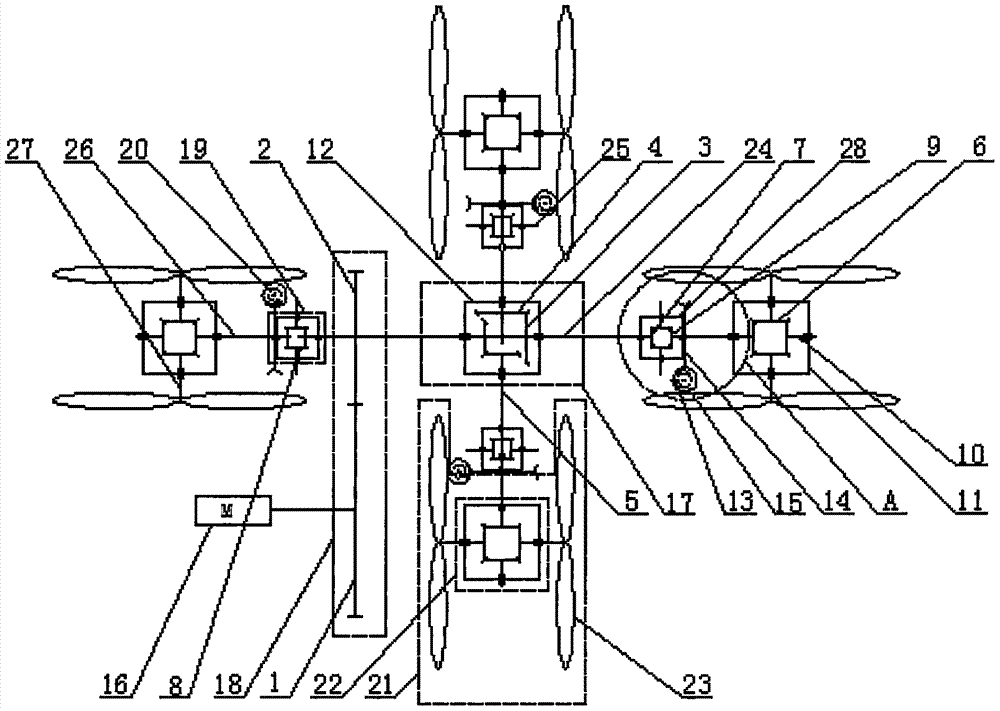
[0016] Specific implementation mode one: as figure 1 and figure 2 As shown, this embodiment discloses an oil-operated bevel gear differential multi-rotor agricultural spraying aircraft, including an engine 16, a central bevel gear transmission box 17, a gear or belt transmission mechanism 18, and four bevel gear differential transmission boxes 19 , four worm and gear transmission mechanisms 20 and four rotor transmission mechanisms 21, each of the rotor transmission mechanisms 21 includes a rotor bevel gear transmission box 22 and two rotor blades 23,

[0017] The output shaft of the engine 16 is fixedly connected with the driving gear 1 in the gear or belt transmission mechanism 18, and the driven gear 2 in the described gear or belt transmission mechanism 18 is fixedly mounted on the horizontal center of the central bevel gear transmission box 17. On the shaft 24, the two ends of the horizontal central axis 24 of the central bevel gear transmission box 17 and the two ends ...

specific Embodiment approach 2

[0020] Specific implementation mode two: as figure 1 and figure 2 As shown, the oil-operated bevel gear differential multi-rotor agricultural spraying aircraft described in Embodiment 1, the central bevel gear transmission box 17 includes a central transmission box body 12, a horizontal central shaft 24, and two central active bevel gears 3. Two central driven bevel gears 4 and two central output shafts 5. Both ends of the horizontal central shaft 24 pass through the central transmission case 12 and are arranged outside the central transmission case 12. The horizontal central shaft 24 and The central transmission box 12 is rotationally connected, the two central driving bevel gears 3 and the two central driven bevel gears 4 are all arranged in the central transmission box 12, and the two central driving bevel gears 3 are fixedly installed in the horizontal center On the shaft 24, each central driving bevel gear 3 meshes with a central driven bevel gear 4, and each said centr...

specific Embodiment approach 3

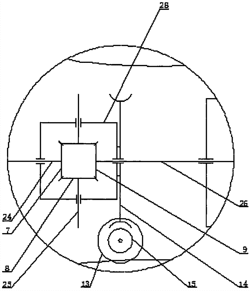
[0021] Specific implementation mode three: as figure 1 and figure 2 As shown, the oil-operated bevel gear differential multi-rotor agricultural spraying aircraft described in Embodiment 1, each of the bevel gear differential transmission boxes 19 includes a bevel gear differential box 28, a bevel gear 7, Bevel gear two 9, two bevel gear three 8 and two bevel gear support shafts 25, the bevel gear one 7, bevel gear two 9 and two bevel gear three 8 are all arranged in the bevel gear differential box 28 , two bevel gear support shafts 25 are respectively rotatably equipped with a bevel gear three 8, and the two bevel gear three 8 are meshed with bevel gear one 7 and bevel gear two 9 at the same time, and the two bevel gear support shafts 25 are all rotatably connected with the side walls of the bevel gear differential case 28.


PUM


Abstract

An oil-operated bevel gear differential multi-rotor agricultural spraying aircraft relates to the technical field of agricultural unmanned aerial vehicles. The invention can realize the purposes of large load capacity, long flight time, good spraying operation quality, high operation efficiency, low operation cost, eliminating phytotoxicity caused by farmers spraying pesticides, and saving labor force. The engine is fixedly connected with the driving gear of the gear or belt transmission mechanism, and the driven gear of the gear transmission mechanism is fixedly mounted on the horizontal central shaft of the central bevel gear transmission box. The horizontal central shaft and the two central output shafts of the central bevel gear transmission box are both Bevel gear 1 and bevel gear 2 of the bevel gear differential transmission box are fixedly connected with the rotor input shaft of the rotor bevel gear transmission box of the rotor transmission mechanism, and the two rotor output shafts of the rotor bevel gear transmission box are fixedly equipped with Rotor, the worm gear in the worm gear transmission mechanism is installed on the rotor input shaft, and the worm is connected with the speed regulating motor. The invention is used in the fields of agricultural spraying operation, aerial inspection, air transportation and the like.

Description

technical field [0001] The invention relates to the technical field of agricultural unmanned aerial vehicles, in particular to an oil-operated bevel gear differential multi-rotor agricultural spraying aircraft, which belongs to the flying platform used in the field of agricultural production. Background technique [0002] With the vigorous development of agriculture, agricultural production puts forward a higher demand for modern agricultural facilities. The advantages of agricultural aviation operations are becoming more and more significant, and their uses are becoming more and more extensive. Aviation operations can also play an important role in the standardization and intensification of agricultural services, ensuring the efficiency of large-scale land production, monitoring the use of pesticides for farmers, preventing natural disasters and pests, and improving the human living environment and ecological balance. [0003] At present, large state-owned farms such as rec...

Claims


Application Information

Patent Timeline
Patent Type & Authority Applications(China)
IPC IPC(8): B64D1/18B64D27/02B64D35/02B64D35/04
CPCB64D1/18B64D27/02B64D35/02B64D35/04B64D2027/026
Inventor 冯江钱秋羽
Owner 冯江
Why Eureka
Try Eureka