

Bulk cargo unloading equipment and multi-shaft driving decelerator thereof
A multi-axis drive, reducer technology, applied in the direction of transmission box, components with teeth, cranes, etc., can solve the problem of low running stability, to ensure smooth running, increase rotational torque, and improve overall running stability Effect
- Summary
- Abstract
- Description
- Claims
- Application Information
AI Technical Summary
Problems solved by technology
Method used
Image

Examples
Embodiment 1
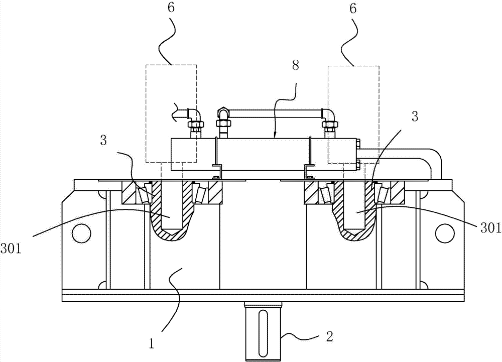
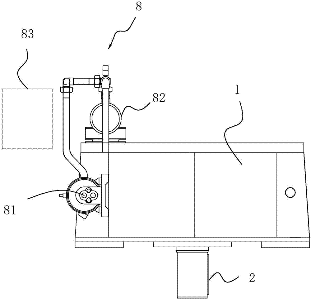
[0044] A multi-axis drive reducer, see figure 1 , including a box body 1, an output shaft 2, and at least two input shafts 3, the ends of each input shaft 3 are connected to a corresponding external power source 6, and all input shafts 3 are transmitted to the The output shaft 2 is used to output rotational power.
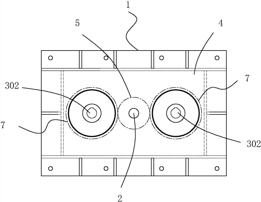
[0045] see figure 1 as well as figure 2 , the inside of the box body 1 is provided with an accommodating chamber 4, one end of the output shaft 2 is located outside the box body 1, and the other end is connected to an output gear 5, and the output gear 5 is located in the accommodating chamber 4. In this embodiment, the input shaft 3 The number is two, and the two ends of each input shaft 3 are respectively a power input end 301 and a power output end 302 located in the accommodation chamber 4. The power input end 301 is used to connect with the external power source 6, and the external power source 6 A motor can be selected, and the input gear 7 is installed o...
Embodiment 2
[0050] A bulk cargo handling equipment, see Figure 4 , comprising a frame 32, on which a turntable 9 is vertically rotatably connected, on the frame 32 is also provided with a rotary drive part 10 for driving the turntable 9 to rotate in a circumferential direction, and the rotary drive part 10 can be selected from a motor, To drive the entire turntable 9 to rotate circumferentially, the turntable 9 is hinged with a main arm 11 arranged horizontally, and the turntable 9 is also provided with a swing arm driving part 30 for driving the main arm 11 to swing up and down around the hinge point , the main arm 11 is provided with a horizontal screw conveying mechanism 12, and the end of the main arm 11 away from the turntable 9 is provided with a vertical screw conveying mechanism 13 docked with the horizontal screw conveying mechanism 12; Rotate in the opposite direction, the swing arm drive part 30 will also drive the main arm 11 to swing up and down, the swing arm drive part 30 ...
Embodiment 3
[0056] Compared with the second embodiment, the internal structure of the main support rod 16 is set differently, see Image 6 as well as Figure 7 , the main support rod 16 includes an active rod 17, a piston sleeve 172, and a driven rod 18; one end of the active rod 17 is hinged to the main arm 11, and the other end is an active piston end 171 that is sealed and slidably connected to the piston sleeve 172, in order to realize The above-mentioned sealed sliding connection, there is a sealing ring between the outer wall of the active piston end 171 and the inner wall of the piston sleeve 172, a one-way air intake valve 27 is arranged on the active piston end 171, and the driven rod 18 is close to the end of the active rod 17 The part is the driven piston end 181 that is connected to the piston sleeve 172 by sealing and sliding. In order to realize the sealing and sliding connection, there is also a sealing ring between the driven piston end 181 and the inner wall of the piston...
PUM
 Abstract
Description
Claims
Application Information