Sintering flue gas mass-divided directional circulation and on-line denitration system

A technology of directional circulation and sintering flue gas, which is applied in the field of flue gas denitrification system in the field of environmental protection, can solve the problems of large investment and high cost of denitrification treatment, and achieve the effect of reducing denitrification cost, reducing resistance loss and reducing load

Active Publication Date: 2017-10-10
WUHAN UNIV OF SCI & TECH +1
View PDF6 Cites 4 Cited by
  • Summary
  • Abstract
  • Description
  • Claims
  • Application Information

AI Technical Summary

Problems solved by technology

[0006] The present invention aims at the common problems existing in the existing sintering flue gas treatment, such as long process route, large investment in denitrification treatment, and high cost, and combines the characteristics of different temperatures and pollutant concentrations of sintering flue gas in different areas of the sintering machine to provide a simple process flow. , no outsourcing denitrification catalyst, high recovery rate of flue dust waste heat, environmental friendliness, low investment in denitrification equipment, low denitrification operation cost, sintering flue gas separation and directional circulation and online denitrification system, online denitrification, realizing denitrification catalyst and flue gas temperature rise Zero investment in energy consumption

Method used


Image

  • Sintering flue gas mass-divided directional circulation and on-line denitration system
  • Sintering flue gas mass-divided directional circulation and on-line denitration system
  • Sintering flue gas mass-divided directional circulation and on-line denitration system

Examples


Embodiment Construction

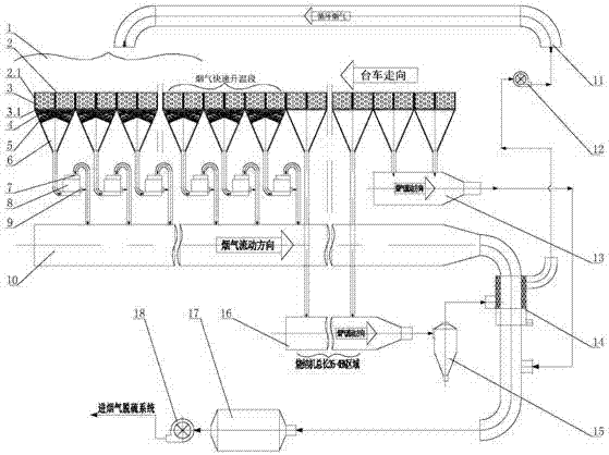
[0029] see figure 2 , the system of the present invention includes a sintering machine 2, a bellows 6 is provided under the trolley 2.1 of the sintering machine 2, and the outlet at the bottom of the bellows 6 is connected to the flue pipe, and the sintering machine 2 is divided into an ignition section, a machine There are four areas: the head section, the flue gas rapid heating section and the tail section. The flue gas pipeline includes the high-temperature flue gas main flue 11 , the circulating flue gas main flue 16 and the nose ignition section flue 13 .

[0030] The air box 6 outlets below the tail section and the flue gas rapid heating section are respectively connected to the high-temperature flue gas main flue 10 through the corresponding fluidized bed reactor 8, and the high-temperature flue gas main flue 10 passes through the flue gas heat exchanger 14. The tube side or shell side is connected to the electrostatic / bag filter 17; the outlet of the bellows 6 below t...


PUM


Abstract

The invention relates to a sintering flue gas mass-divided directional circulation and on-line denitration system. According to the technical scheme, the sintering flue gas mass-divided directional circulation and on-line denitration system comprises a sintering machine. Air boxes are arranged below trolleys of the sintering machine, and bottom outlets of the air boxes communicate with a gas flue pipeline. The sintering machine is divided into an ignition section, a machine head section, a flue gas fast heating section and a machine tail section in sequence in the advancing direction of the trolleys. The gas flue pipeline comprises a high temperature flue gas main flue, a circulatory flue gas main flue and a machine head ignition section flue. The outlets of the air boxes below the machine tail section and the flue gas fast heating section communicate with the high temperature flue gas main flue through fluidized bed reactors separately, the outlets of the air boxes below the machine head section communicate with a circulatory flue gas cover on the trolleys of the sintering machine through the circulatory flue gas main flue, and the outlets of the air boxes below the ignition section are connected with the machine head ignition section flue. The sintering flue gas mass-divided directional circulation and on-line denitration system is simple, compact in structure, high in waste heat recovery rate and low in denitration operation cost, denitration equipment investment is saved, and zero input of denitration catalysts and flue gas heating energy consumption is achieved.

Description

technical field [0001] The invention relates to a flue gas denitrification system in the field of environmental protection, in particular to a sintering flue gas separation and directional circulation and on-line denitrification system. Background technique [0002] Sintering flue gas is the dusty exhaust gas produced during the high-temperature sintering molding process after the sintering mixture is ignited and runs with the trolley. Due to the high air leakage rate (40%-50%) and high solid material circulation rate of domestic sintering machines, a considerable part of the air does not pass through the sintering material layer, and about 4000-6000m3 of sintered ore produced per ton 3 smoke. The main characteristics of sintering flue gas are: large amount of flue gas, high temperature, high dust content, high CO content, sulfur dioxide (SO 2 ) with low concentration, high moisture content, corrosive gas, and dioxin-like substances. Because the sintering flue gas emissio...

Claims


Application Information

Patent Timeline
Patent Type & Authority Applications(China)
IPC IPC(8): F27D17/00B01D53/90B01D53/56B01D46/02
CPCB01D46/02B01D53/56B01D53/90B01D2251/2062B01D2258/0283F27D17/00F27D17/008
Inventor 秦林波吴高明吴晓晖韩军卫书杰
Owner WUHAN UNIV OF SCI & TECH
Why Eureka
Try Eureka