
Glass light guide plate and manufacturing method thereof

A technology of glass light guide plate and manufacturing method, which is applied in the direction of light guide, optics, optical components, etc., which can solve the problems of low cutting utilization rate, high price, complicated liquid crystal display assembly process, etc., and achieve the effect of optimizing uniformity

Pending Publication Date: 2017-10-10
青岛国骐光电科技有限公司
View PDF6 Cites 1 Cited by
  • Summary
  • Abstract
  • Description
  • Claims
  • Application Information

AI Technical Summary

Problems solved by technology

The current quantum film is composed of upper and lower PET sheets, and uniformly coated quantum dots in the middle are laminated. The existing liquid crystal display assembly process is complicated, the price is high, and the cutting utilization rate is low.

Method used


Image

  • Glass light guide plate and manufacturing method thereof
  • Glass light guide plate and manufacturing method thereof
  • Glass light guide plate and manufacturing method thereof

Examples


Embodiment 1

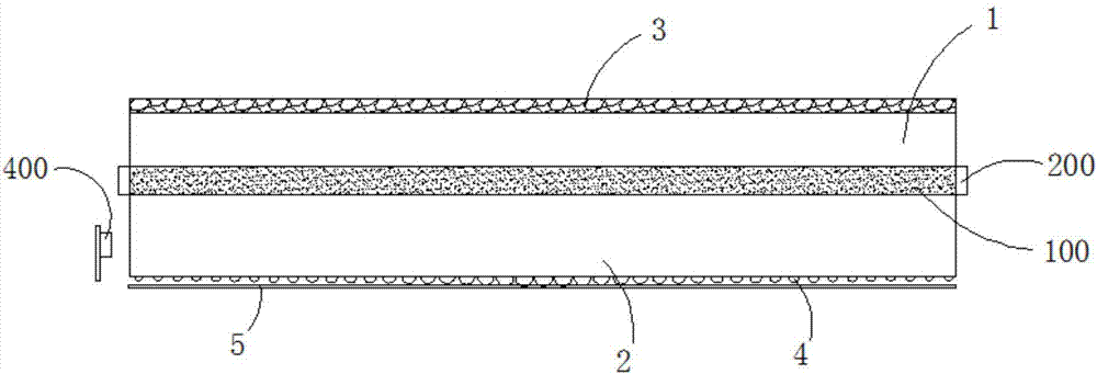
[0023] Embodiment 1: as figure 1 and image 3 As shown, a glass light guide plate in this embodiment includes an upper glass 1 and a lower glass 2, the lower surface of the upper glass 1 and the upper surface of the lower glass 2 are bonded together, and the lower surface of the upper glass 1 is vacuum The way of vapor deposition is coated with uniform quantum dots 100; the upper surface of the upper glass 1 is coated with a diffusion layer 3 for diffusing and atomizing the light, and the lower surface of the lower glass 2 is provided with a layer for converting the line light source It is the optical dot layer 4 of the surface light source. The thickness of the lower glass 2 is 0.5mm-2mm, and the thickness of the upper glass 1 is 0.3mm-1mm, which mainly serve to protect the quantum dots 100 .

[0024] Preferably, the upper glass 1 and the lower glass 2 are bonded by glass glue 200, the width of the glass glue 200 is 3-4mm, and counting inward from the edge of the upper glas...

Embodiment 2

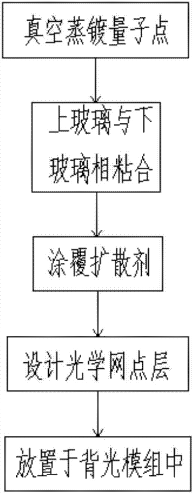
[0030] Embodiment 2: as figure 2 and image 3 Shown, a kind of manufacturing method of glass light guide plate of the present embodiment, it comprises

[0031] Coating the quantum dots 100 on the lower surface of the upper glass 1 by vacuum evaporation; and the temperature of the vacuum evaporation is lower than or equal to 60 degrees Celsius;

[0032] In the vacuum chamber, the lower surface of the upper glass 1 and the upper surface of the lower glass 2 are bonded together with glass glue 200, and the width of the glass glue 200 is 3-4mm, counting from the edge of the upper glass 1 and the lower glass 2 inwards ; The main components of glass glue 200 are sodium silicate and organic silicone;

[0033] A diffusing agent for diffusing and atomizing the light is coated on the upper surface of the upper glass 1 by roller coating;

[0034] Design the optical dot layer 4 and print ink on the lower surface of the lower glass 2; the arrangement of the optical dots in the optical ...


PUM

PropertyMeasurementUnit
Thicknessaaaaaaaaaa
Thicknessaaaaaaaaaa

Abstract

The invention relates to a glass light guide plate and a manufacturing method thereof. The glass light guide plate comprises upper glass and lower glass, wherein the lower surface of the upper glass is attached to the upper surface of the lower glass; uniform quantum dots are coated on the lower surface of the upper glass in a vacuum evaporation manner; a diffusion layer used for diffusing and atomizing light rays is coated on the upper surface of the upper glass; and an optical dot layer used for converting a line light source into an area source is arranged on the lower surface of the lower glass. The glass light guide plate is widely applied to an edge-lighting backlight module of a blue LED lamp and replaces the traditional PMMA (Polymethyl Methacrylate) or MS light guide plates, quantum films are replaced, and aluminum backplanes are canceled, so that the TV module is developed to be ultrathin and ultra-high-definition; meanwhile, the properties of the light guide plate are remained, the optical dot design can be performed on the premise of optimizing the macroscopic color saturation, the uniformity of the picture is optimized, and the glass light guide plate has significances in ultrathin and ultrahigh color range TV modules.

Description

technical field [0001] The invention relates to a glass light guide plate and a manufacturing method thereof. Background technique [0002] Traditional LCD TVs use acrylic light guide plates, which are generally 2-4mm thick. With the addition of aluminum backplanes, the overall thickness will exceed 1cm, which makes it difficult for designers to reduce the thickness of the TV; but the latest structure uses glass For the light guide plate, the glass light guide plate and the reflector are bonded together with UV-cured pressure-sensitive adhesive to form the light guide plate assembly. The optical and mechanical properties of this assembly are better than the traditional acrylic light guide plate assembly; The high mechanical performance of itself can eliminate the use of the aluminum back plate, making the LCD TV thinner, the thinnest can be less than 5mm, reducing the thickness of the TV by 70% and the weight of the TV by 30%. On existing liquid crystal displays, as the req...

Claims


Application Information

Patent Timeline
IPC IPC(8): G02B6/00G02F1/13357
CPCG02F1/133606G02B6/0043G02B6/005G02B6/0051G02B6/0065G02F1/133607G02F1/133614
Inventor 王晓张子宾张健
Owner 青岛国骐光电科技有限公司
Learn More