Passenger car series-parallel hybrid transmission

A transmission and hybrid technology, applied in power plants, hybrid vehicles, pneumatic power plants, etc., can solve problems such as low efficiency and achieve high transmission efficiency, easy cost control, and flexible layout.

Active Publication Date: 2019-12-13
BEIJING INSTITUTE OF TECHNOLOGYGY
View PDF4 Cites 0 Cited by
  • Summary
  • Abstract
  • Description
  • Claims
  • Application Information

AI Technical Summary

Problems solved by technology

The hybrid power system in series form can ensure that the engine works in the economical range, and is suitable for working conditions such as frequent start and stop, severe load changes, and urban driving; but for high-speed stable working conditions, due to one more energy conversion, the efficiency is low

Method used


Image

  • Passenger car series-parallel hybrid transmission
  • Passenger car series-parallel hybrid transmission
  • Passenger car series-parallel hybrid transmission

Examples


Embodiment 1

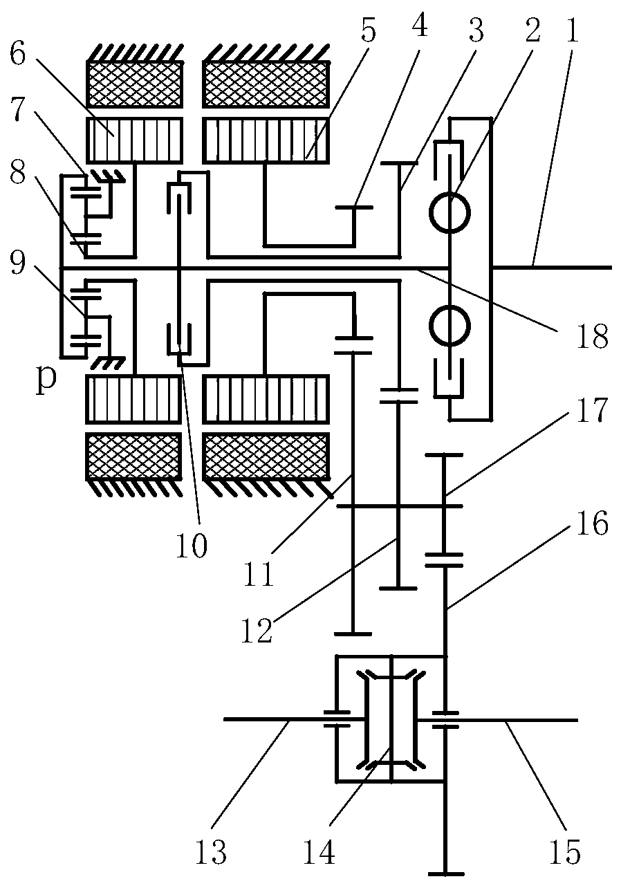
[0028] This embodiment provides a series-parallel hybrid power transmission device suitable for passenger vehicles, such as figure 1 As shown, the transmission device includes: an input shaft 18, a shock absorber 2, a clutch 10, a speed-increasing planetary row, a differential 14, an electric motor 5, a generator 6 and a plurality of gears. Wherein, the electric motor 5 and the generator 6 are coaxially arranged, the speed-increasing planetary row is arranged on the side where the generator 6 is located, and the clutch 10 is located between the motor 5 and the generator 6, and the connection relationship is: one end of the input shaft 18 passes through the shock absorber 2 Connect the engine input shaft 1, and the other end is sequentially connected with the driving end of the clutch 10 and the ring gear 7 of the speed-up planetary row, the planet carrier 9 of the speed-up planetary row brakes, the rotor of the generator 6 and the sun Round 8 connections.

[0029] The rotor o...

Embodiment 2

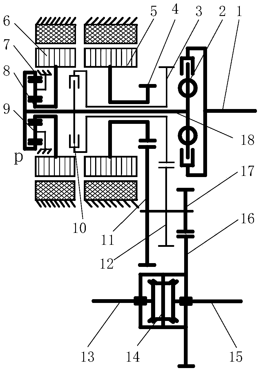
[0033] like Figure 4 shown, with figure 1 The difference of Embodiment 1 shown is that the clutch 10 is arranged at the input end, its driving end is connected with the input shaft 18 , and its driven end is connected with the gear A3. The arrangement of the clutch 10 at the input end can simplify the number of sleeve shaft layers, that is, only the gear shaft of the gear B4 is coaxially sleeved outside the input shaft 18, but the axial length will be increased.

[0034] In the above two embodiments, the generator and the motor are coaxially arranged, and the speed-increasing planetary row is arranged on the side of the generator, so as to increase the speed of the generator and increase the power density of the generator. The power of the electric motor is transmitted to the differential through two pairs of fixed shaft gears to drive the wheels on both sides. After the clutch is engaged, the power of the engine is transmitted to the differential through another pair of fi...


PUM


Abstract

The invention discloses a serial-parallel hybrid power transmission device for a passenger car, wherein only one clutch is disposed; an in-parallel working condition is achieved; acceleration of a power generator is carried out by a planet row; speed reduction and torque increase of an electric motor is achieved by a fixed-shaft gear; and the structure and technologies are simple, so the cost can be controlled easily. The hybrid power transmission device comprises an input shaft, a damper, the clutch, the acceleration planet row, a differential mechanism, the electric motor, the power generator and a fixed-shaft gear transmission mechanism. Start, low-speed and middle-speed working conditions are driven by pure electric driving or serial-parallel hybrid power driving; the car is driven separately by the electric motor; and the power of electric motor can come from a battery pack or the power generator. Under the working condition of serial-parallel power, an engine drives the power generator to generate power by the acceleration planet row. At this moment, the power generator can work in an economic oil consumption interval, and surplus electric energy can be stored in the battery pack. Under the direct drive working condition of engine, the clutch is connected and power of the engine directly drives car travelling, so that an energy transformation course can be reduced, and transmission efficiency can be increased.

Description

technical field [0001] The invention relates to a transmission device, in particular to a series-parallel hybrid power transmission device, which belongs to the technical field of power transmission. Background technique [0002] Hybrid transmission technology is an important means of energy saving and emission reduction for passenger vehicles, and major automobile manufacturers are actively developing it. Toyota's THS hybrid technology has a good fuel-saving effect. The planetary mechanism is used for power splitting to ensure that the engine always works in the economical range, but the planetary mechanism has higher requirements. The hybrid power system in series form can ensure that the engine works in the economical range, which is suitable for frequent start and stop, severe load changes, urban driving and other working conditions; but for high-speed stable working conditions, due to one more energy conversion, the efficiency is low. The parallel hybrid power system i...

Claims


Application Information

Patent Timeline
Patent Type & Authority Patents(China)
IPC IPC(8): B60K6/365B60K6/38B60K6/40B60K6/442B60K6/50B60L50/15
CPCB60K6/365B60K6/38B60K6/40B60K6/442B60K6/50B60L50/15Y02T10/62Y02T10/7072
Inventor 彭增雄胡纪滨魏超李学良
Owner BEIJING INSTITUTE OF TECHNOLOGYGY
Why Eureka
Try Eureka