Denitrification system and replacement method of catalyst layers thereof

A catalyst layer and catalyst technology, applied in chemical instruments and methods, separation methods, dispersed particle separation, etc., can solve the problems of poor adaptability of the reactor flow field, increased power consumption of induced draft fans, and increased operating costs, etc., to reduce fan power consumption. consumption and operating costs, avoiding poor adaptability of the flow field, and avoiding the effect of long-term shutdown

Pending Publication Date: 2017-10-17
LONGKING COALOGIX ENVIRONMENTAL PROTECTION TECH SHANGHAI CO LTD
View PDF4 Cites 1 Cited by
  • Summary
  • Abstract
  • Description
  • Claims
  • Application Information

AI Technical Summary

Problems solved by technology

However, although the addition of a spare layer catalyst can improve the denitrification efficiency, it also brings many adverse effects
After adding a spare layer catalyst, due to the increase in the total thickness of the catalyst layer, the resistance of the SCR denitrification system will increase by about 200Pa. The increase in resistance will lead to an increase in the power consumption of the induced draft fan and increase the operating cost. At the same time, the original two-layer catalyst The degree of mechanical wear increases and the reproducibility decreases; after layering, SO 2 / SO 3 The conversion rate of the reactor will increase, which will easily lead to corrosion of the downstream air preheater; and the adaptability of the flow field in the reactor will be worse after adding layers, which will easily cause dust deposition

Method used


Image

  • Denitrification system and replacement method of catalyst layers thereof
  • Denitrification system and replacement method of catalyst layers thereof

Examples


Embodiment Construction

[0032] In order to more clearly illustrate the embodiments of the present invention or the technical solutions in the prior art, the specific implementation manners of the present invention will be described below with reference to the accompanying drawings. Obviously, the accompanying drawings in the following description are only some embodiments of the present invention, and those skilled in the art can obtain other accompanying drawings based on these drawings and obtain other implementations. In order to make the drawing concise, the parts related to the present invention are only schematically shown in each drawing, and they do not represent the actual structure of the product.

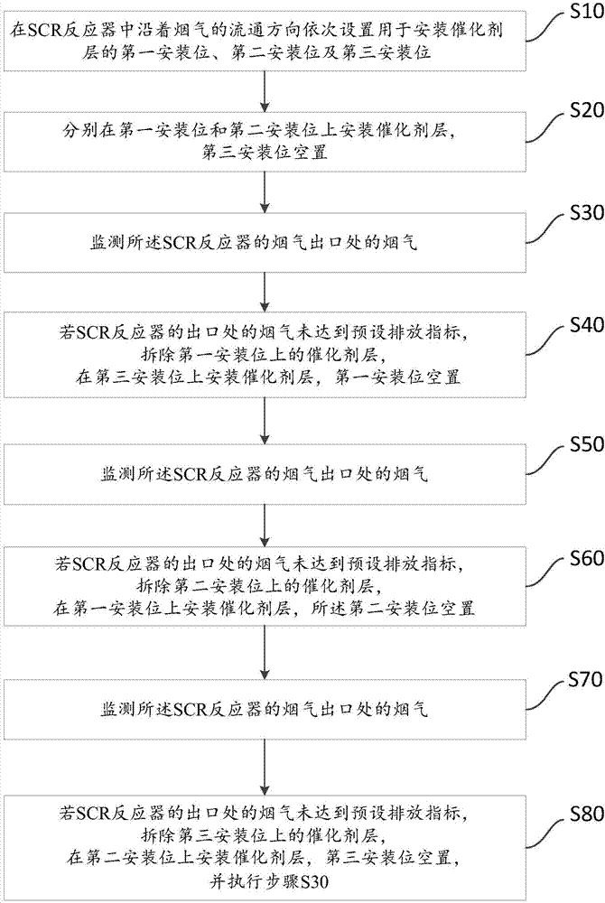
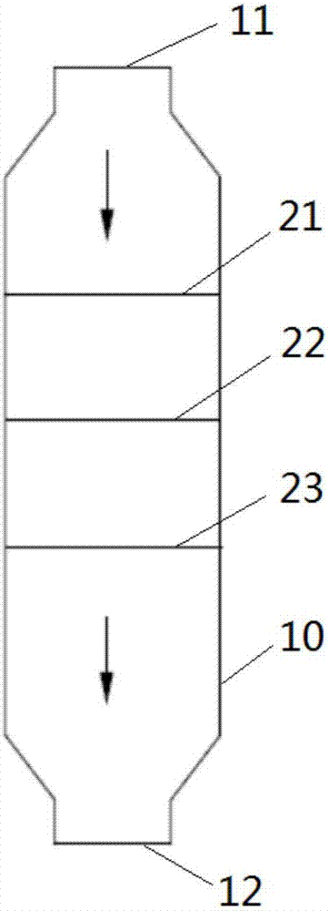
[0033] Such as figure 1 As shown, this specific embodiment discloses a method for replacing the catalyst layer in the denitrification system, including steps:

[0034] S10: sequentially setting the first installation position, the second installation position and the third installation positio...


PUM


Abstract

The invention discloses a denitrification system and a replacement method of catalyst layers thereof. The replacement method comprises the following steps: S10: in an SCR (selective catalytic reduction) reactor, sequentially arranging a first mounting position, a second mounting position and a third mounting position for mounting the catalyst layer in the flow direction of flue gas; S20: mounting the catalyst layers on the first mounting position and the second mounting position, and emptying the third mounting position; S30: monitoring outlet flue gas; S40: if the outlet flue gas is not up to standard, detaching the catalyst layer on the first mounting position and mounting the catalyst layer on the third mounting position; S50: monitoring outlet flue gas; S60: if the outlet flue gas is not up to standard, detaching the catalyst layer on the second mounting position and mounting the catalyst layer on the first mounting position; S70: monitoring outlet flue gas; S80: if the outlet flue gas is not up to standard, detaching the catalyst layer on the third mounting position, mounting the catalyst layer on the second mounting position and executing the step S30. By the replacement method, a nitrogen oxide emission index is met, the internal resistance of the system is reduced, dust accumulation in the reactor and corrosion to downstream equipment are reduced, and the catalyst replacing expense is reduced.

Description

technical field [0001] The invention relates to a method for replacing a catalyst layer in an SCR denitration system, in particular to a denitration system and a method for replacing a catalyst layer. Background technique [0002] The principle of Selective Catalytic Reduction (SCR) is that under the action of a catalyst, the reducing agent NH 3 Selectively convert NO and NO at 290-400°C 2 reduced to N 2 , while NH hardly occurs 3 with O 2 oxidation reaction, thereby increasing the N 2 selectivity, reducing the NH 3 consumption. [0003] In order to meet the long-term stability of the NOx concentration at the outlet of the denitrification SCR device ≤ 50mg / Nm 3 According to the environmental protection requirements, it is the most common practice to add a spare layer catalyst. However, although the addition of a spare layer catalyst can improve the denitrification efficiency, it also brings many adverse effects. After adding a spare layer catalyst, due to the increa...

Claims


Application Information

Patent Timeline
Patent Type & Authority Applications(China)
IPC IPC(8): B01D53/88B01D53/90B01D53/56B01D53/96
CPCB01D53/8631B01D53/88B01D53/90B01D53/96B01D2255/9025
Inventor 单文盼张伟蒋慧王若凯索静
Owner LONGKING COALOGIX ENVIRONMENTAL PROTECTION TECH SHANGHAI CO LTD
Why Eureka
Try Eureka