Scintillation crystal unit sheet, array module, and detector

A scintillation crystal array and scintillation crystal technology, which is applied to scintillation components, instruments, measuring devices, etc., can solve the problems of square module cutting size deviation, increased production cost, and large-length cutting size deviation, so as to avoid defective products, Improve measurement accuracy and reliability, avoid mutual influence effects

Active Publication Date: 2017-10-17
FUJIAN INST OF RES ON THE STRUCTURE OF MATTER CHINESE ACAD OF SCI
View PDF8 Cites 3 Cited by
  • Summary
  • Abstract
  • Description
  • Claims
  • Application Information

AI Technical Summary

Problems solved by technology

Liquid photosensitive curing glue or epoxy glue is usually used when pasting the crystal sheet and the reflective film. Before the glue is cured, the crystals inside the module will easily slip due to mutual extrusion and friction, resulting in offset.
This will make the scintillation crystal detector module partially unable to identify the position of the crystal, resulting in defective products
During the production process, the sliding problem of the reflective film in the scintillation crystal module cannot be found with the naked eye, nor can it be observed from the outside with the help of an observation instrument. We can only wait for the UV glue or epoxy glue to cure and use experimental methods to measure it. In addition, there is no other better way to deal with the sliding problem of the reflective film in the scintillation crystal array during the production process
After the glue was cured, it was found that the reflective film had slipped and shifted. At this time, it was no longer possible to take effective remedial measures for the scintillation crystal module.
[0005] In addition, there is another problem in the conventional technology, the formed square module is prone to cutting size deviation during the cutting process
At present, most of the multi-wire cutting machines used in crystal cutting have the problem that the cutting size of the long length will be offset, and this problem is due to mechanical reasons, which cannot be overcome by design or tooling
Therefore, it will be difficult to solve the problem of cutting size deviation produced by conventional technology, and such deviation will make the whole piece cut out unusable, resulting in a large number of waste pieces
This will greatly increase the production cost, and ultimately affect the production success rate of the array module

Method used


Image

  • Scintillation crystal unit sheet, array module, and detector
  • Scintillation crystal unit sheet, array module, and detector
  • Scintillation crystal unit sheet, array module, and detector

Examples


Embodiment 1

[0038] Embodiment 1 Scintillation crystal unit chip

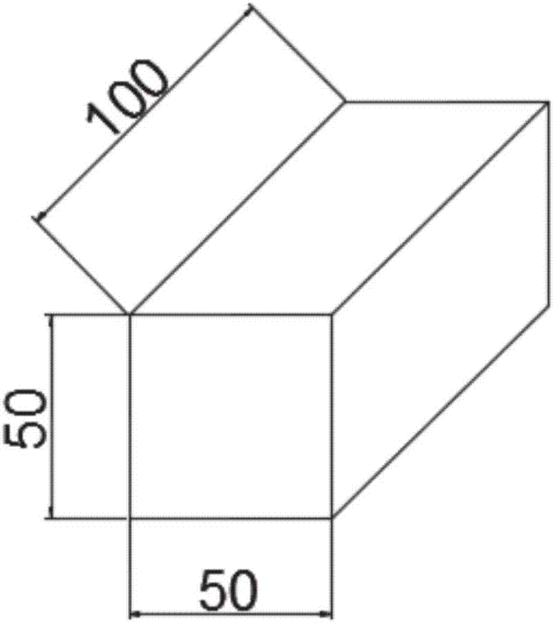
[0039] The size of the scintillation crystal in this embodiment is 50mm*50mm*100mm, see figure 1 , where the end face of 50mm*50mm is the clear surface, and the rest of the face is the side.

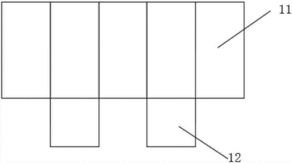
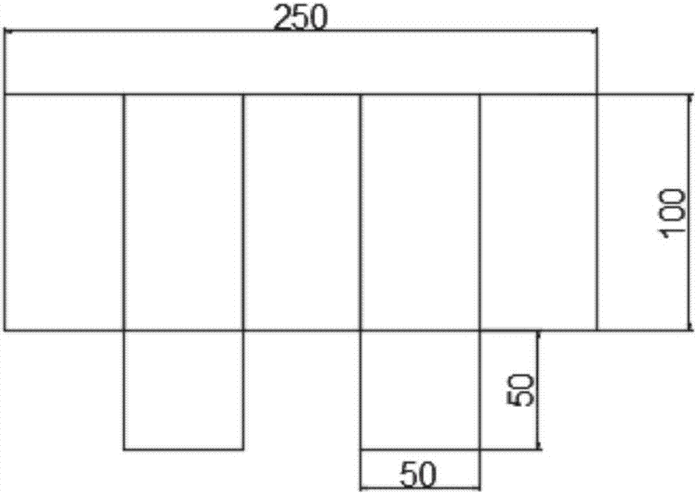
[0040] In this embodiment, the inclusion is a reflective film unit, such as figure 2 As shown, it is composed of a main body part 11 and a positioning part 12, the size of the main body part 11 is 250mm*100mm, and the size of the positioning part 12 is 50mm*50mm.

[0041] Apply glue evenly on each side of the scintillation crystal and the light-transmitting surface perpendicular to the side, and the reflective film unit presses figure 2 and image 3 The shown creases are turned over to form an upward concave space 21 and a downward concave space 22, see Figure 4 .

[0042] Arrange the glued crystals neatly in the concave space formed by the reflective film unit, bond the sides of the scintillation crystals to the main body 11 ...

Embodiment 2

[0044] Embodiment 2 scintillation crystal array module

[0045] Making two scintillation crystal units A1 of Embodiment 1 # , put two scintillation crystal units A1 according to Figure 7 Stacked in the same way, and glue is applied between the two scintillation crystal units, and clamped by precision vise clamps. Figure 7 The main body part 71 of the reflective film unit in the upper and lower two scintillation crystal unit pieces wraps four scintillation crystals 72 respectively. After curing, a scintillation crystal array module of 100mm*100mm*100mm can be obtained, such as Figure 8 As shown, the main body part 81 of the reflective film unit in the upper and lower scintillation crystal unit pieces wraps four scintillation crystals 82 respectively. The obtained scintillation crystal array module is denoted as B1 # .

[0046] It should be noted that, in this embodiment, after the side surface of the crystal unit is pasted to the main body of the reflective film, the li...

Embodiment 3

[0047] Embodiment 3 scintillation crystal array module

[0048] The manufacturing method of the scintillation crystal unit sheet is the same as that of the embodiment 1, and the manufacturing method of the scintillation crystal array module is the same as that of the embodiment 2, except that parameters such as the scintillation crystals, size, and number of array components are different. See Table 1 for details.

[0049] Table 1

[0050] Array module serial number


PUM


Abstract

The invention discloses a scintillation crystal unit sheet, an array module, and a detector. The scintillation crystal unit sheet comprises a scintillation crystal and a wrapping body. The wrapping body is provided with at least one concave part, and the scintillation crystal is disposed in the concave part. A scintillation crystal array is formed arranging a plurality of crystal units according to a preset design to form crystal unit sheets, and the crystal unit sheets are arranged to form the crystal array module. Each of the crystal unit sheets is formed by disposing each crystal unit on a reflection film in a wrapped manner, and then epoxy glue is used for solidification. The crystal unit sheets are arranged according to the preset design to form the array module, and are solidified by using the epoxy glue. A production method of a scintillation crystal detector array module has advantages of high flexibility, tidy arrangement, compact structure, and easy production.

Description

technical field [0001] The application relates to a scintillation crystal detector array module, which belongs to the field of scintillation crystal detection. Background technique [0002] Scintillation crystal detector is a scintillation detector that uses the flash of ionizing radiation to detect in certain substances. It has the characteristics of high detection efficiency and short resolution, and is widely used in nuclear medicine, safety inspection, high-energy physics and cosmic ray detection. researching. Scintillation crystal detectors usually use scintillation crystals that can effectively block and absorb electromagnetic radiation and produce luminescence with electromagnetic radiation as detection materials. The scintillation crystal detector module is composed of some single crystal arrays of the same size, and a reflective film is sandwiched between each crystal to achieve the light splitting effect, which is used to identify the position of each crystal. ...

Claims


Application Information

Patent Timeline
Patent Type & Authority Applications(China)
IPC IPC(8): G01T1/00
CPCG01T1/003
Inventor 吴少凡郑熠黄鑫
Owner FUJIAN INST OF RES ON THE STRUCTURE OF MATTER CHINESE ACAD OF SCI
Why Eureka
Try Eureka