
Optimal control method for electric vehicle range extender

An electric vehicle, optimized control technology, applied in the direction of electric controllers, controllers with specific characteristics, etc., can solve the problems of complex control structure and lack of robustness of the system, and achieve simplified coordinate transformation, improved power generation efficiency, and improved stability performance and robustness

Active Publication Date: 2021-02-12
北京共元科技有限公司
View PDF11 Cites 0 Cited by
  • Summary
  • Abstract
  • Description
  • Claims
  • Application Information

AI Technical Summary

Problems solved by technology

[0005] Technical route 2 is to use PI controller to control the power of the system, and use voltage and current sensors to calculate the power feedback value. Since the current loop using PI control contains current coupling items, compensation items need to be added to ensure the dynamic performance of the current loop, resulting in The system control structure is complex and lacks robustness. Some literatures also give robust control methods, such as fuzzy logic control, and the control method using DP technology to obtain the optimal solution
However, these control strategies, such as the DP algorithm, are not suitable for real-time control, because this control method is based on the calculation of multiple driving cycles, thus requiring a large amount of data processing

Method used


Image

  • Optimal control method for electric vehicle range extender
  • Optimal control method for electric vehicle range extender
  • Optimal control method for electric vehicle range extender

Examples


Embodiment

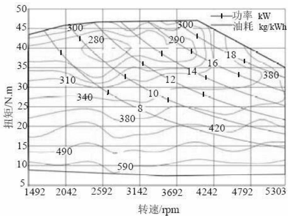
[0060] The ER system of this embodiment is aimed at the application of urban compact electric vehicles. According to the vehicle development goals and performance requirements, the system is finally determined to consist of a 17kW two-cylinder four-stroke engine, a 13kW permanent magnet synchronous generator and a PWM converter. image 3 In order to select the characteristic curve of the engine, since the permanent magnet synchronous generator can achieve an output efficiency of more than 90% in the working area of ​​​​more than 70%, and the high-efficiency working area of ​​the engine is much narrower than that of the generator, so the analysis determines the engine's output efficiency. The lowest fuel consumption working area can realize the matching of the high efficiency work of the ER system.

[0061] according to image 3 The characteristic curve of the engine can approximately fit a third-order speed-torque function relationship curve, such as Figure 4 Shown by the r...


PUM


Abstract

The invention relates to an optimal control method for a range extender of an electric vehicle, and designs a multi-stage power following control method suitable for the operation of a range-extended electric vehicle in cities. The control process is as follows: First, according to the current operating conditions of the electric vehicle, determine the working area with the lowest fuel consumption, and select one of the N operating points for matching; determine the current power demand value and actual power value, and adjust the range extender Control the output power, determine the current demand value of the range extender in the static coordinate system, and finally control the working current of the range extender according to the current demand value; based on the switching of the engine at N operating points, the speed point will be switched accordingly , so the output frequency of the generator will also work stably at N frequency points ω according to the change of the rotational speed 1 , ω 2 … ω N . Therefore, the present invention simplifies the coordinate transformation of the control process, and improves the stability, robustness and real-time tracking characteristics of the system.

Description

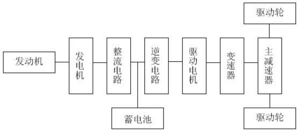
Technical field: [0001] The invention relates to a hybrid electric vehicle, and further relates to an optimal control method for a range extender of the electric vehicle. Background technique: [0002] In order to overcome the shortcoming of a pure electric vehicle (Electric Vehicle, EV) with insufficient range, more and more types of electric vehicles have been defined and developed. Extended Ranger Electrical Vehicle (EREV) is considered as a low-cost solution. EREV mainly has three structural forms: battery power generation system, fuel cell system, engine and generator combination system. Among them, the engine and generator combined power generation system is the most widely used, and a small generator set is integrated inside it. The structural diagram of the power system is shown in the attachment figure 1 shown. The difference between EREV and HEV hybrid electric vehicle (Hybrid Electric Vehicle, HEV) is that the power output part of HEV is directly connected to t...

Claims


Application Information

Patent Timeline
Patent Type & Authority Patents(China)
IPC IPC(8): G05B11/42
CPCG05B11/42
Inventor 孙强吕海英王莎莎杜艳红张伟玉
Owner 北京共元科技有限公司
Learn More