Uniform-light micro-optic resonance waste gas treatment device

A waste gas treatment device and low-light technology, which are applied in gas treatment, membrane technology, dispersed particle separation, etc., can solve the problems of uneven distribution, high purification capacity, low purification efficiency, etc., and achieve obvious purification effect and improve purification efficiency. , the effect of compressing the space occupancy rate

Pending Publication Date: 2017-10-20
长兴博易环保科技有限公司
View PDF2 Cites 2 Cited by
  • Summary
  • Abstract
  • Description
  • Claims
  • Application Information

AI Technical Summary

Problems solved by technology

[0008] 1. Since the ultraviolet rays irradiated by the lamp tube are diffusive, and the photocatalyst plate is a planar structure, the middle part of the photocatalyst plate is close to the lamp tube, and its edge is far away from the lamp tube, so the light intensity obtained in the middle part is much greater than that in the edge part, resulting in the photocatalyst

Method used


Image

  • Uniform-light micro-optic resonance waste gas treatment device
  • Uniform-light micro-optic resonance waste gas treatment device
  • Uniform-light micro-optic resonance waste gas treatment device

Examples


Example Embodiment

[0034] The present invention will be further described below in conjunction with the drawings.

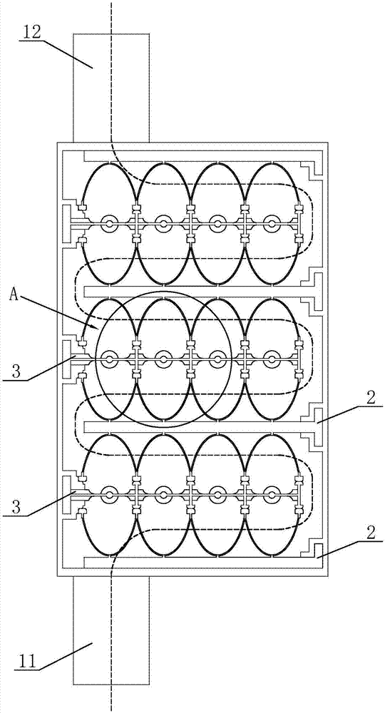
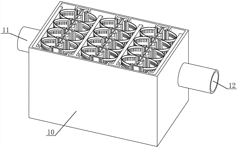
[0035] Such as figure 1 with image 3 The shown long-diameter low-light resonance exhaust gas treatment device includes a housing 10, an air inlet pipe 11, and an air outlet pipe 12. The air inlet pipe 11 and the air outlet pipe 12 are fixed at both ends of the housing 10; the housing 10 is provided with a plurality of staggered ultraviolet components 3 and photocatalyst assembly 2.

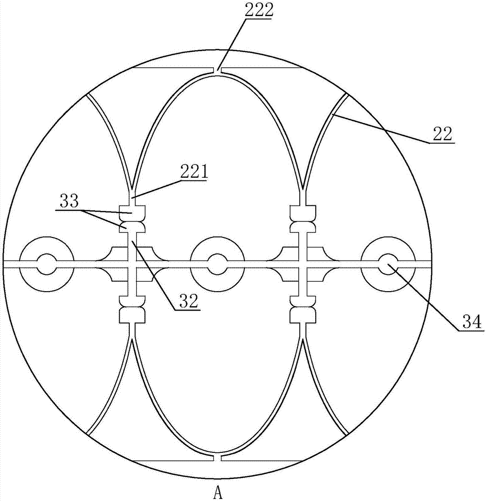
[0036] Such as Figure 5 As shown, the photocatalyst assembly 2 includes a plate frame 20 and a photocatalyst plate 22. The photocatalyst plate 22 is fixed on the surface of the plate frame 20. The photocatalyst plate 22 is a semicircular or parabolic air-permeable mesh plate; the plate frame 20 is an air-impermeable plate shape Structure, the end of the photocatalyst plate 22 close to the lamp holder 30 is the low beam end 221, the two ends close to the plate frame 20 are the high beam end 222, and the ai...


PUM


Abstract

The invention discloses a device for treating waste gas with homogeneous light and low-light resonant resonance, which comprises a casing, an air inlet pipe and an air outlet pipe. The casing is provided with a plurality of staggered ultraviolet components and photocatalyst components. The components include a plate frame and a photocatalyst plate. The photocatalyst plate is a breathable mesh plate; both the plate frame and the light frame are airtight plate-shaped structures, and an air flow channel for exhaust gas is formed between the light frame and the plate frame. The photocatalyst plate is located in the air flow channel. Inside, the photocatalyst plate is semicircular or parabolic. By setting the photocatalyst plate in the channel through which the exhaust gas passes, the ring-shaped photocatalyst plate completely surrounds the ultraviolet lamp tube, which can get sufficient light to generate a large amount of ozone and free hydroxyl groups. The exhaust gas passes through the photocatalyst plate. The ozone and hydroxyl generated on both sides of the photocatalyst plate are taken away together, so that the exhaust gas is fully purified, and the staggered arrangement of the lamp holder and the plate holder extends the path of exhaust gas purification, and the exhaust gas purification is more thorough.

Description

technical field [0001] The invention belongs to the technical field of waste gas treatment, and in particular relates to a treatment device for uniform light and micro-light resonant waste gas. Background technique [0002] With the current development of industry and commerce and the enhancement of environmental protection awareness, the deteriorating living environment has attracted the general attention of the public and the industry. Among them, due to the vigorous development of industry, air pollution spreads rapidly, and harmful exhaust gas spreads over a large area. The pollutants directly harm people's health through the respiratory system. In response to this development trend, various technologies and equipment related to environmental protection engineering have been continuously developed. The purification treatment of industrial waste gas is one of the most important issues faced in many environmental protection cases. [0003] At present, the industry mainly ...

Claims


Application Information

Patent Timeline
IPC IPC(8): B01D53/88
CPCB01D53/885B01D2251/104B01D2259/804B01D2259/806
Inventor 贾建洪周士晖陶嘉贵张玉华
Owner 长兴博易环保科技有限公司
Why Eureka
Try Eureka