Heat exchange device for fresh air ventilator

A technology of heat exchange device and fresh air blower, which is applied in the field of air purification, can solve the problems of large space occupation, and achieve the effect of saving electric energy, reducing energy consumption, and good purification effect

Pending Publication Date: 2017-10-20
SICHUAN JIANYUAN ENERGY SAVING TECH CO LTD
View PDF6 Cites 0 Cited by
  • Summary
  • Abstract
  • Description
  • Claims
  • Application Information

AI Technical Summary

Problems solved by technology

[0003] The purpose of the present invention is to provide a heat exchange device for fresh air fans, which solves the problem of separate heat recovery and sterilization in the prior art and relatively large space occupation

Method used


Image

  • Heat exchange device for fresh air ventilator
  • Heat exchange device for fresh air ventilator

Examples


Embodiment 1

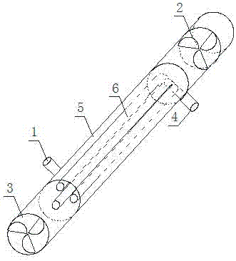
[0025] This embodiment provides a heat exchange device for a new fan, such as figure 1 and 2 , comprising a housing and an outdoor air inlet 1, a fresh air outlet 2, a dirty air inlet 4 and a dirty air outlet arranged on the housing,

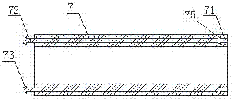
[0026] The housing is provided with a heat exchange box 5 connected to the outdoor air inlet 1 and the fresh air outlet 2, the heat exchange box 5 is provided with a heat exchange tube 6, and the outer surface of the heat exchange tube 6 is provided with an ultraviolet emitting component , and coated with a photocatalyst sterilizing layer, the two ends of the heat exchange tube 6 are respectively communicated with the dirty air inlet 4 and the dirty air outlet;

[0027] The outdoor air inlet 1 is provided with a filter membrane, and the filter membrane includes a primary filter membrane, a HEPA high-efficiency filter membrane, and an activated carbon adsorption membrane arranged in sequence along the air flow direction;

[0028] The fresh air ...

Embodiment 2

[0031] This embodiment is based on the embodiment 1, and further defines that: the outdoor air inlet 1 and the dirty air outlet 3 are respectively connected to the outlet of the blower. Improve the efficiency and effect of air purification and speed up air circulation.

Embodiment 3

[0033] This embodiment is based on the embodiment 1, and further defines that: the fresh air outlet 2 is provided with a temperature control device and a humidity adjustment device. Inevitably there will be loss in the heat exchange process, so whether it is refrigeration or heating, the gas flowing out from the fresh air outlet 2 after heat exchange cannot be at the same temperature as the room, so a temperature control device is still needed. In addition, adjusting indoor humidity can improve human comfort.


PUM


Abstract

The invention discloses a heat exchange device for a fresh air ventilator. The heat exchange device for the fresh air ventilator comprises a shell, an outdoor air inlet, a fresh air outlet, a contaminated air inlet and a contaminated air outlet, wherein the outdoor air inlet, the fresh air outlet, the contaminated air inlet and the contaminated air outlet are formed in the shell. A heat exchange tank which communicates the outdoor air inlet with the fresh air outlet is arranged in the shell. A heat exchange pipe is arranged in the heat exchange tank. The outer surface of the heat exchange pipe is provided with an ultraviolet ray emitting component and coated with a photocatalyst sterilization layer. The two ends of the heat exchange pipe communicate with the contaminated air inlet and the contaminated air outlet correspondingly. The fresh air outlet is connected with a gas pipeline. The end face of one end of the gas pipeline is provided with an annular groove. The end face of the other end of the gas pipeline and the end face of the fresh air outlet are provided with annular protrusions. The inner side wall and the outer side wall of the protrusions are provided with limiting rings. The groove is matched with the protrusions. The outer wall of the heat exchange pipe is coated with a photocatalyst sterilization layer and provided with a light source, so that harmful substances like various bacteria and germs in fresh air are killed. Compared with a device with a single photocatalyst sterilization layer, the heat exchange device for the fresh air ventilator has a better purification effect.

Description

technical field [0001] The invention relates to the field of air purification, in particular to a heat exchange device for a fresh fan. Background technique [0002] The fresh air fan is an effective air purification equipment that can circulate the indoor air. On the one hand, the indoor dirty air is discharged outside, and on the other hand, the fresh outdoor air is sterilized, disinfected, filtered and other measures, and then input into the room. , so that the room is full of fresh and clean air at all times. The fresh air fan uses the patented technology of fresh air convection to achieve convection of the indoor air through independent air supply and induction, thereby maximizing the indoor air replacement. The fresh air fan is built-in The multifunctional purification system ensures that the air entering the room is clean and healthy. Contents of the invention [0003] The purpose of the present invention is to provide a heat exchange device for a fresh air fan, wh...

Claims


Application Information

Patent Timeline
Patent Type & Authority Applications(China)
IPC IPC(8): F24F12/00F24F13/30
CPCF24F12/006F24F13/30
Inventor 徐斌斌
Owner SICHUAN JIANYUAN ENERGY SAVING TECH CO LTD
Why Eureka
Try Eureka