
Detection system and method for six-degree-of-freedom spatial position and attitude

A technology of spatial position and detection system, which is applied in the direction of navigation, measurement device, surveying and navigation through speed/acceleration measurement, which can solve the problems of poor mobility and portability, low accuracy, and limited detection range, etc., and achieve improvement Accuracy and stability, increased range, improved mobility and portability effects

Inactive Publication Date: 2017-10-20
GUANGZHOU ALUBI ELECTRONICS TECH CO LTD
View PDF14 Cites 14 Cited by
  • Summary
  • Abstract
  • Description
  • Claims
  • Application Information

AI Technical Summary

Problems solved by technology

[0003] Existing research on spatial position and attitude detection technology mostly uses a single sensor detection method, such as inertial sensor, electromagnetic sensor, optical camera or laser sensor. Since there is only one detection method, this type of research often exists. Problems such as low accuracy, limited detection space range, easy to be affected by occlusion, or limited detection data
In addition, there are some studies that use the combination of optical camera and other sensors. This type of research uses the low-frequency information of the optical camera and the high-frequency information of other sensors to ensure the accuracy of the finally obtained spatial position and attitude data. However, due to the The optical camera in this kind of research needs to be installed around the target object, so there is still the problem of being easily affected by occlusion, and because the camera is fixed, the detection range is greatly limited, and the mobility and portability are relatively poor.

Method used


Image

  • Detection system and method for six-degree-of-freedom spatial position and attitude
  • Detection system and method for six-degree-of-freedom spatial position and attitude
  • Detection system and method for six-degree-of-freedom spatial position and attitude

Examples


Embodiment 1

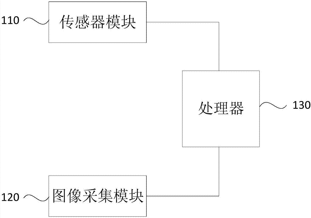
[0031] figure 1 It is a schematic structural diagram of a 6-DOF spatial position and attitude detection system provided by Embodiment 1 of the present invention. Such as figure 1 As shown, the detection system includes:

[0032] The sensor module 110, the image acquisition module 120 and the processor 130, the sensor module 110 and the image acquisition module 120 are all set on the measured object; the sensor module 110 and the image acquisition module 120 are respectively connected to the processor 130.

[0033] Different from the traditional installation method, in this embodiment, both the sensor module 110 and the image acquisition module 120 are installed on the object to be measured. Monitor the movement of the measured target.

[0034] In this embodiment, the sensor module 110 is preferably connected to the processor 130 through an SPI or I2C interface; the image acquisition module 120 is preferably connected to the processor 130 through a USB interface circuit.

...

Embodiment 2

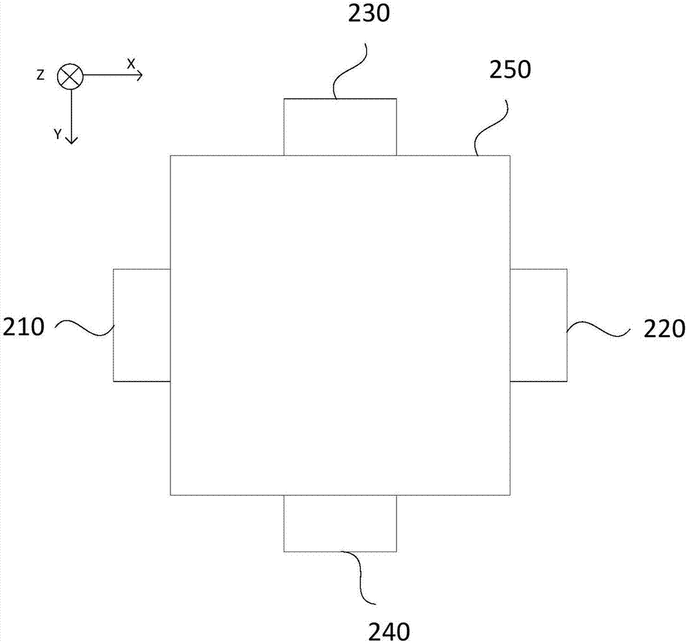
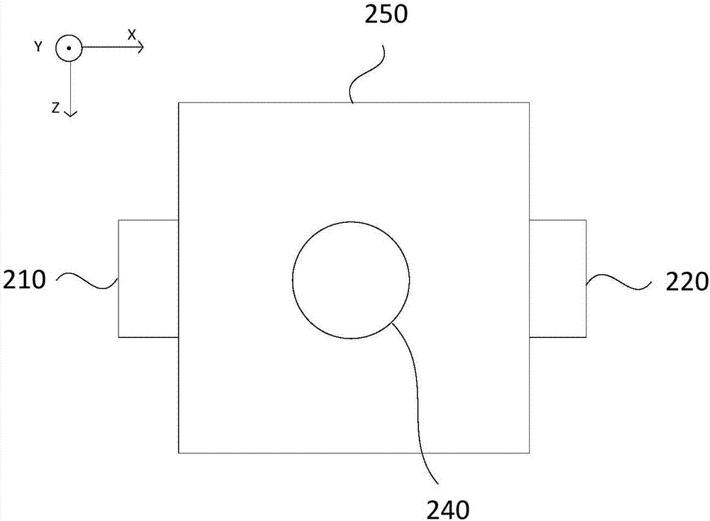
[0045] Figure 2a It is a structural top view of a 6-DOF spatial position and attitude detection system provided by Embodiment 2 of the present invention, Figure 2b It is a structural front view of a 6-DOF spatial position and attitude detection system provided by Embodiment 2 of the present invention, Figure 2a with Figure 2b The coordinate system shown in is the coordinate system of the sensor module. This embodiment is optimized on the basis of Embodiment 1, such as Figure 2a with 2b as shown,

[0046] The four sides of the detection system respectively include at least one camera.

[0047] In this embodiment, preferably, the sensor module, the image acquisition module and the processor can be integrated into a whole. Wherein, the detection system casing 250 can preferably be packaged into a cube or a cuboid shape, preferably the sensor module and the processor can be packaged inside the cube or cuboid shape detection system casing 250, wherein the sensor module can...

Embodiment 3

[0053] image 3 It is a flow chart of a method for detecting a 6-degree-of-freedom space position and attitude provided by Embodiment 3 of the present invention. The method can be executed by the processor of the detection system for a 6-degree-of-freedom space position and attitude in each of the above-mentioned embodiments, including :

[0054] Step 310, receiving raw data, the raw data includes sensory data and image data related to the position and posture of the measured object.

[0055] In this embodiment, the processor receives raw data, the raw data includes acceleration, angular velocity, distribution of magnetic field and image data, and the accelerometer, gyroscope, magnetometer and image acquisition module in the sensor module in each of the above-mentioned embodiments The cameras in are acquired and sent separately.

[0056] Step 320, performing data calibration, fusion or mutual compensation processing on the original data to obtain 6-DOF space position and att...


PUM


Abstract

Embodiments of the invention provide a detection system and method for six-degree-of-freedom spatial position and attitude. The detection system comprises a sensor module, an image acquisition module and a processor, wherein the sensor module and the image acquisition module are both arranged on a to-be-detected target. Since the sensor module and the image acquisition module are both arranged on the to-be-detected target, the mobility and portability of the system are improved; the image acquisition module moves along with the movement of the to-be-detected target, so the detection scope of data acquisition is broadened; the image acquisition module acquires the image data of a surrounding environment instead of the movement of the target, so the problem that the image data of the target cannot be used due to shielding is overcome; meanwhile, processing is carried out on high-frequency data acquired by the sensor module and low-frequency data acquired by the image acquisition module, so the accuracy and stability of target data are improved, and high-precision detection of the six-degree-of-freedom spatial position and attitude of the to-be-detected target is realized.

Description

technical field [0001] Embodiments of the present invention relate to the technical field of spatial position and attitude detection, and in particular to a detection system and method for a 6-degree-of-freedom spatial position and attitude. Background technique [0002] In recent years, with the development of spatial position and attitude detection technology, this technology has been more and more widely used in technical fields such as auxiliary sports training, augmented reality, medical rehabilitation assistance, industrial equipment detection, and human-computer interaction. [0003] Existing research on spatial position and attitude detection technology mostly uses a single sensor detection method, such as inertial sensor, electromagnetic sensor, optical camera or laser sensor. Since there is only one detection method, this type of research often exists. Problems such as low accuracy, limited detection space range, susceptibility to occlusion, or limited detection da...

Claims


Application Information

Patent Timeline
Patent Type & Authority Applications(China)
IPC IPC(8): G01C21/16
CPCG01C21/165
Inventor 林焯华
Owner GUANGZHOU ALUBI ELECTRONICS TECH CO LTD
Learn More