Industrial robot speed reducer torsion rigidity testing stand

An industrial robot and torsional stiffness technology, which is applied in the testing of machine gear/transmission mechanism, the testing of machine/structural components, and the testing of mechanical components, etc. It can solve the problems of taking up too much space, scattered test benches, and large test benches. , to achieve the effect of high degree of automation, easy replacement, and high test efficiency

Inactive Publication Date: 2017-10-20
芜湖赛宝机器人产业技术研究院有限公司
View PDF4 Cites 6 Cited by
  • Summary
  • Abstract
  • Description
  • Claims
  • Application Information

AI Technical Summary

Problems solved by technology

[0006] (1) The test benches are scattered. If you want to perform all measurements on the same precision reducer, you need to replace multiple test benches, which is cumbersome and time-consuming;
[0007] (2) A single test bench is la

Method used


Image

  • Industrial robot speed reducer torsion rigidity testing stand

Examples


Embodiment Construction

[0022] The embodiments of the present invention will be described in detail below with reference to the accompanying drawings, but the present invention can be implemented in many different ways defined and covered by the claims.

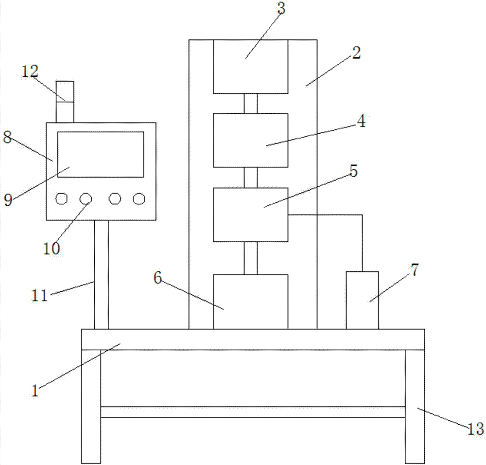
[0023] Such as figure 1 As shown, an industrial robot reducer torsional rigidity test bench includes a support platform 1, a vertical plate 2, a drive motor 3, an electric dynamometer 6, a reducer 4, a torsion sensor 5, a circular grating 7 and a controller 8. The vertical plate 2 is installed on the upper side of the support platform 1, and the driving motor 3, the reducer 4, the torsion sensor 5 and the electric dynamometer 6 are installed on the vertical plate 2 in sequence from top to bottom. The central shaft is connected to the reducer 4, the reducer 4 is connected to the torsion sensor 5 through the coupling, the torsion sensor 5 is connected to the electric dynamometer 6 through the coupling, and the torsion sensor 5 is connected to the circ...


PUM


Abstract

The invention relates to the technical field of an industrial robot speed reducer and particularly relates to an industrial robot speed reducer torsion rigidity testing stand. A vertical board is mounted at an upper side end of a supporting stand, a driving motor, a speed reducer, a torsion sensor and an electric dynamometer are sequentially mounted on the vertical board from up to down, a center rotation shaft of the driving motor is connected with the speed reducer, the speed reducer is connected with the torsion sensor through a shaft coupling, the torsion sensor is connected with the electric dynamometer through the shaft coupling, the torsion sensor is connected with a circular grating through a program control wire, and the torsion sensor, the driving motor and the electric dynamometer are connected with a controller through program control wires. The industrial robot speed reducer torsion rigidity testing stand is advantaged in that torsion loading for a power unit is carried out through the electric dynamometer, magnitude of an application torque can be automatically adjusted, a radial force loading unit is employed to simulate a radial force of the power unit of the industrial robot in a start or operation process, and magnitude of applied radial force can be automatically adjusted.

Description

technical field [0001] The invention relates to the technical field of industrial robot reducers, in particular to an industrial robot reducer torsional rigidity test bench. Background technique [0002] The servo motor of the industrial robot power unit has the characteristics of small inertia, fast response speed, and low maintenance and maintenance requirements; the reducer of the industrial robot power unit is one of the key technologies of industrial robots, with high transmission stiffness, large transmission ratio, and small inertia. , large output torque, stable transmission, small size, strong impact resistance, etc. [0003] The power unit of the industrial robot is installed in the narrow space inside the joint arm of the industrial robot, which has slow heat dissipation, easy vibration, harsh working environment, and prone to failure. The industrial robot power unit reliability test bench can simulate its actual working conditions and conduct reliability tests, ...

Claims


Application Information

Patent Timeline
IPC IPC(8): G01M13/02
CPCG01M13/027
Inventor 李骁侯卫国卫能张永杰涂志健
Owner 芜湖赛宝机器人产业技术研究院有限公司
Why Eureka
Try Eureka