A cabin air purification device

An air purification device and purification device technology, applied in the field of air purification, can solve the problems of short service life, high personnel density, and high cost of use of air purifiers, and achieve the effect of restoring absorption and purification capacity, good purification effect, and low cost

Active Publication Date: 2019-11-08
DALIAN INST OF CHEM PHYSICS CHINESE ACAD OF SCI
View PDF6 Cites 0 Cited by
  • Summary
  • Abstract
  • Description
  • Claims
  • Application Information

AI Technical Summary

Problems solved by technology

The power consumption of this process is relatively high, because there are both water pumps and fans working at the same time, but the purification effect is relatively good
The fifth type of air purifier is a combination of the above methods to obtain better results, but the cost increases
For manned vehicles, due to its running acceleration, direction change and vibration, and the high density of people, the service life of general household air purifiers in the cabin is very short, especially the consumables for dust removal and adsorption of pollutants , must be replaced at the end of a single stroke to maintain the air purification effect, resulting in high cost of use
In addition, air purifiers containing liquid or water as the purification medium are difficult to use on such vehicles

Method used


Image

  • A cabin air purification device
  • A cabin air purification device
  • A cabin air purification device

Examples


Embodiment 1

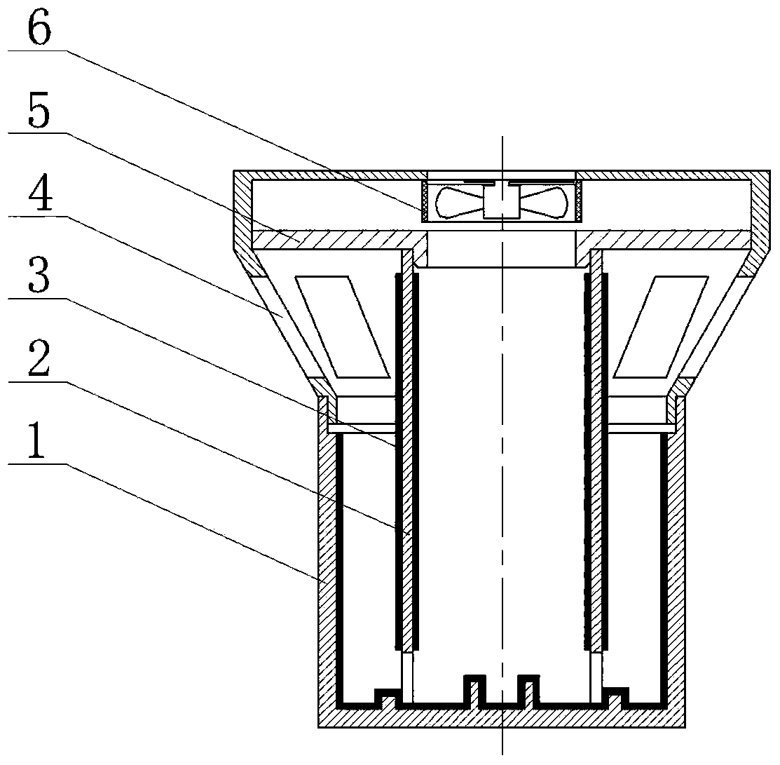
[0046] An air purification device in a cabin, comprising a container 1, a cylindrical carrier 2, a casing 4, a partition 5, a fan 6 and a soft gel 3, and the soft gel 3 is evenly coated on both sides of the side wall of the cylindrical carrier , the inner wall of the container, the bottom of the container or two or more of the concentric ring platforms, such as figure 1 shown.

[0047] Described container 1 is a cylindrical flat-bottomed open container (inner diameter 100mm, high 120mm); Container 1 bottom is provided with 1 concentric ring platform, and the height of concentric ring platform is 10 millimeters, and width is 1 millimeter. A cylindrical carrier 2 is vertically placed inside the container 1. The cylindrical carrier 2 is a hollow cylinder (inner diameter 65mm, height 180mm) with both ends open. Hole, the bottom of the cylinder wall is provided with 8 strip-shaped slots vertically along the axial direction as ventilation holes, and the ventilation holes connect th...

Embodiment 2

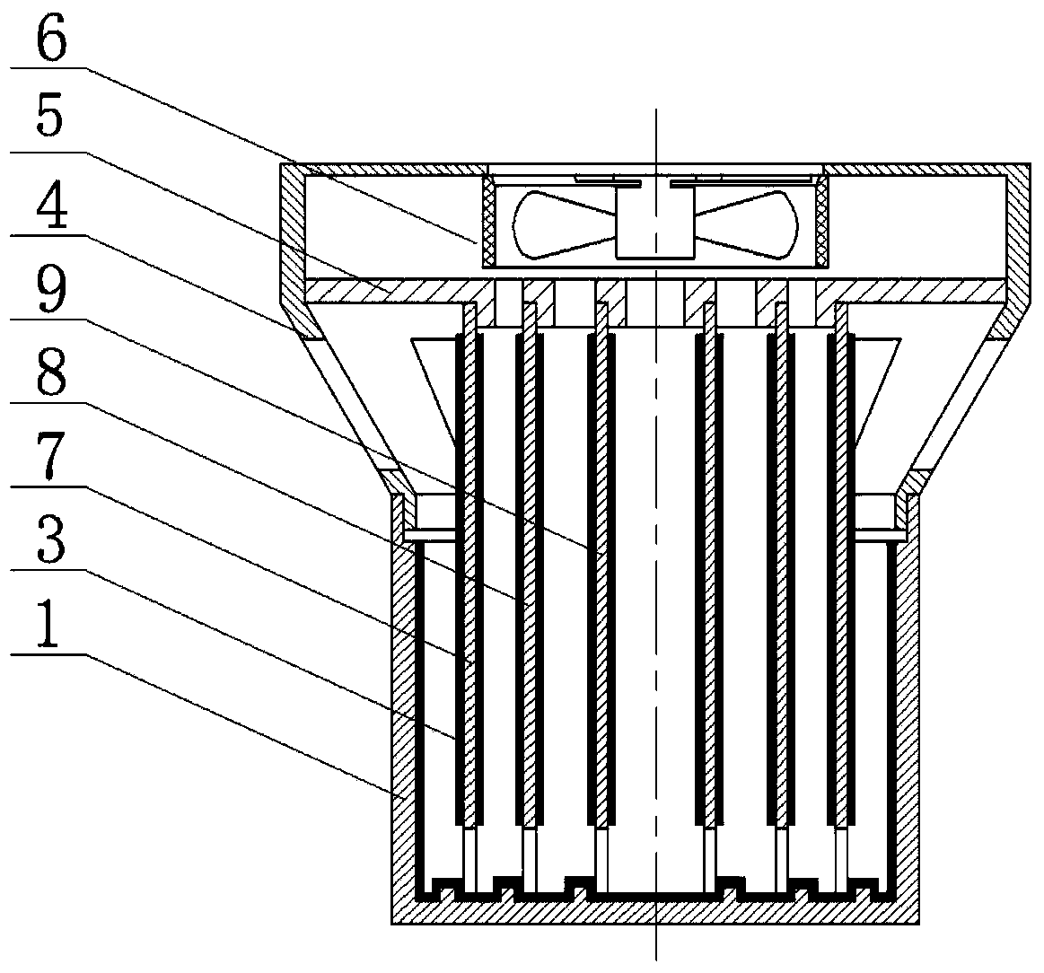
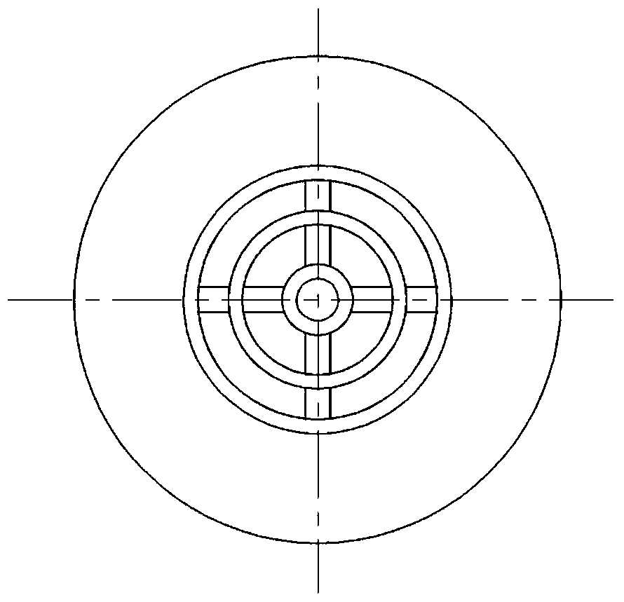
[0051] Compared with the device described in Example 1, the difference is that the inner diameter of the container 1 is 400mm, and there are 3 ring-shaped clamping stations at the bottom, and 3 cylindrical carriers with different diameters are coaxially placed in the container 1 from the center to the outside. ;like figure 2 shown. Wherein, the lower end of the shell 4 is in the shape of a rounded frustum, and an air outlet is provided on the side of the rounded frustum, the diameter of the upper cone is 500 mm, and the lower cone closely matches the opening of the container 1 . In this device, the partition plate 5 is provided with three annular slots, respectively fixing the corresponding cylindrical carrier, and fixing it with a cross-shaped beam. The cross section of the partition plate is as follows: image 3 shown.

Embodiment 3

[0053] Compared with the device described in Embodiment 1, the difference lies in that the lower end of the shell 4 is cylindrical, and the diameter of the upper end is consistent. The side of the cylindrical carrier 2 is provided with dense small holes for easy attachment of the soft gel. There are 2 concentric ring platforms at the bottom of the container 1, and the device is as Figure 4 shown.


PUM

PropertyMeasurementUnit
heightaaaaaaaaaa
widthaaaaaaaaaa
diameteraaaaaaaaaa

Abstract

The invention relates to the technical field of air purification, in particular to an air purification device in a cabin, which is a device that uses a fan to strengthen air flow and uses soft gel to absorb particulate matter and harmful pollutants in the air. The invention uses a fan to blow air over the cylindrical carrier coated with soft gel and the surface of the inner wall of the container, so that the air flow collides and diffuses with the surface of the soft gel multiple times, and absorbs and removes the particulate matter, aerosol and harmful components in the air. Dissolves in soft gel. Replacing the soft gel can regain the purification adsorption capacity. The soft gel can be washed and removed, and then a new soft gel can be applied to the side wall of the cylindrical carrier, the inner wall of the container, the bottom of the container and / or the concentric ring platform by dipping or brushing. The device of the invention has a simple structure, the soft gel used is low in cost, easy to replace, and has obvious purification effect. The air purifying device of the present invention is suitable for purifying the air in cabins on manned transport vehicles such as automobiles, ships, and airplanes.

Description

technical field [0001] The invention relates to the technical field of air purification, in particular to an air purification device in a cabin, which is a device that utilizes a fan to enhance air flow and uses soft gel to absorb particulate matter and harmful pollutants in the air. Background technique [0002] Most of the traditional air purifiers use filter membrane filtration to achieve the purpose of adsorbing particulate matter and harmful gases and purifying the air. At present, most of the filter-type air purifiers on the market use a high-efficiency particulate air filter (HEPA membrane) plus an adsorbent. Although the membrane can prevent particles larger than 0.3 microns, the filter membrane will quickly fail in heavily polluted environments, requiring regular replacement, high cost, and power consumption of more than tens of watts. Another type of air purifier based on electrostatic adsorption uses high-voltage static electricity to positively charge particles ...

Claims


Application Information

Patent Timeline
Patent Type & Authority Patents(China)
IPC IPC(8): B01D49/00B01D53/02B01D53/14
CPCB01D49/00B01D53/02B01D53/14B01D2252/20B01D2252/40B01D2252/504B01D2253/20B01D2253/202B01D2258/06B01D2259/126B01D2259/4508B01D2259/4566B01D2259/4575Y02A50/2351
Inventor 关亚风段春凤田晓静
Owner DALIAN INST OF CHEM PHYSICS CHINESE ACAD OF SCI
Why Eureka
Try Eureka