


Quick Research
Generate reliable direction feasibility study reports for your R&D in just a few steps.

Technical Q&A
Discover and master advanced knowledge NOW. Basics, ideas, possibilities, all at once.

Find Solutions
As an expert in R&D theories, this can generate solutions to your technical problems instantly.

Evaluate Feasibility
Analyze your overall solution with one click, know your potential R&D risks in advance.

Monitor Landscape
Get weekly tech updates, stay abreast of the latest tech innovations and key insights.
Micro-channel heat dissipation chip and preparation method thereof
A technology of micro-fluid channel and micro-fluid channel, which is applied in the field of micro-channel heat dissipation chip and its preparation, can solve the problems of uncontrollable liquid flow rate and structural limitation, and achieve the effect of precise control of heat dissipation effect and low cost
- Summary
- Abstract
- Description
- Claims
- Application Information
AI Technical Summary
Problems solved by technology
Method used
Image

Examples
Embodiment 1
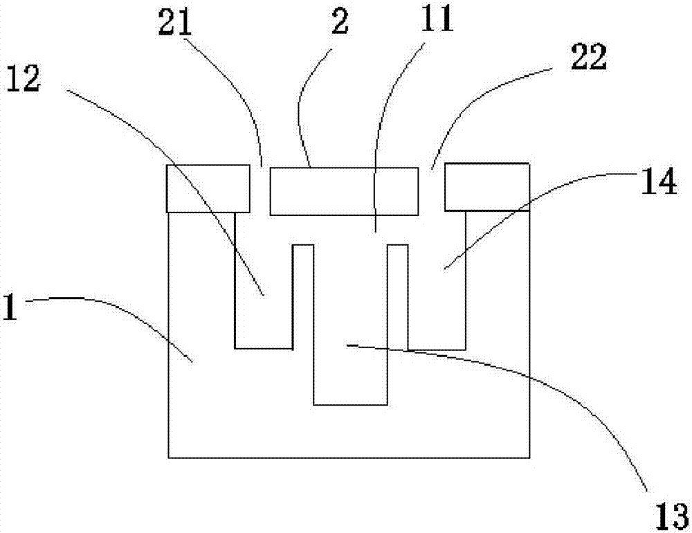
[0031] refer to figure 1 The micro-channel heat dissipation chip provided in this embodiment includes a silicon base body 1 and an isolation layer 2 disposed on the silicon base body 1 . The isolation layer 2 is used to isolate the silicon base body 1 from the liquid flowing through the silicon base body 1 , preferably, the isolation layer 2 is pyrex7740 glass. Wherein, the thickness of the silicon base body 1 is not greater than 1.5 mm, preferably, the thickness of the silicon base body 1 is 500 microns to 1500 microns.
[0032] The top of the silicon basic body 1 is provided with an isolation groove 11, and the isolation groove 11 extends downwards from the first microfluidic channel 12, the second microfluidic channel 13 and the third microfluidic channel 14, which can be arranged according to the actual heat dissipation requirements. The number of the second microfluidic channels 13 is set. The depth of the second microfluidic channel 13 is less than the thickness of the...
Embodiment 2
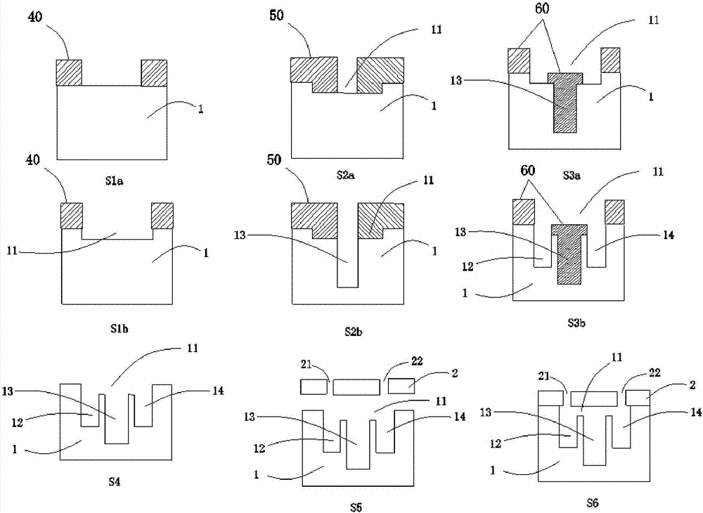
[0048] This embodiment provides another preparation method for the above-mentioned microfluidic heat dissipation chip. The difference between this preparation method and the preparation method in Example 1 is that the formation sequence of the isolation groove 11 and the second microfluidic channel 13 is different. .
[0049] refer to image 3 (S1-S6), the preparation method of the microfluidic cooling chip provided in this embodiment comprises the following steps:
[0050] Step S1, coating photoresist 40 on the top of the silicon basic body 1 (refer to image 3 (S1a) shown), using the photoresist 40 as a mask, etching the top of the silicon base body 1 to form an isolation groove 11 (refer to image 3 (S1b)).
[0051] Step S2, remove the photoresist 40 on the top of the silicon base body 1 in step S1, and recoat the photoresist 50 on the top of the silicon base body 1 formed with the isolation groove 11 (refer to image 3 (shown in S2a), using the photoresist 50 as a mask...
Embodiment 3
[0059] This embodiment provides yet another preparation method for the above-mentioned microfluidic heat dissipation chip, the difference between this preparation method and the preparation method in Example 2 is that the first microfluidic channel 12 and the third microfluidic channel 14 The formation order of the second microfluidic channel 13 is different.
[0060] refer to Figure 4 (S1-S6), the preparation method of the microfluidic cooling chip provided in this embodiment comprises the following steps:
[0061] Step S1, coating photoresist 70 on the top of the silicon base body 1 (refer to Figure 4 (S1a) shown), using the photoresist 70 as a mask, etching the top of the silicon base body 1 to form an isolation groove 11 (refer to Figure 4 (S1b)).
[0062] Step S2, remove the photoresist 70 on the top of the silicon base body 1 in step S1, and recoat the photoresist 80 on the top of the silicon base body 1 formed with the isolation groove 11 (refer to Figure 4 (sho...
PUM
| Property | Measurement | Unit |
|---|---|---|
| Thickness | aaaaa | aaaaa |
| Depth | aaaaa | aaaaa |
| Size | aaaaa | aaaaa |
Abstract
Description
Claims
Application Information
 - R&D Engineer
- R&D Manager
- IP Professional
- Industry Leading Data Capabilities
- Powerful AI technology
- Patent DNA Extraction
Browse by: Latest US Patents, China's latest patents, Technical Efficacy Thesaurus, Application Domain, Technology Topic, Popular Technical Reports.
© 2024 PatSnap. All rights reserved.Legal|Privacy policy|Modern Slavery Act Transparency Statement|Sitemap|About US| Contact US: help@patsnap.com