
Energy storage electric cylinder

An electric cylinder and energy storage technology, applied in the field of mechanical transmission, can solve the problems of waste of ability to provide kinetic energy, waste of energy, not being used, etc., and achieve the effects of increasing work efficiency, reducing costs, and improving response speed.

Active Publication Date: 2017-10-24
NANJING TONYS AUTOMATION TECH CO LTD
View PDF6 Cites 13 Cited by
  • Summary
  • Abstract
  • Description
  • Claims
  • Application Information

AI Technical Summary

Problems solved by technology

[0005] All the above-mentioned electric cylinders are designed for a special application, and each has its own application characteristics, but the thrust of all the above-mentioned electric cylinders is provided by the motor. In some vertical working conditions, the conveyed objects Or the gravitational potential energy of the frame itself is not only not used in the working process, but the motor also provides energy to offset the gravitational potential energy of the conveyed object or frame, which causes a lot of waste of energy; in addition, in some single-stroke In working conditions, the ability of the motor to provide kinetic energy in the idle stroke is also wasted. Therefore, there is an urgent need for an electric cylinder that can store energy and release energy when needed, and there is no such product on the market

Method used


Image

  • Energy storage electric cylinder
  • Energy storage electric cylinder
  • Energy storage electric cylinder

Examples


Embodiment Construction

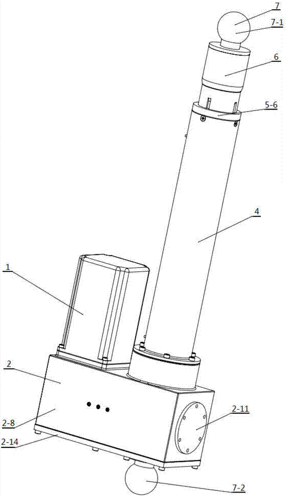
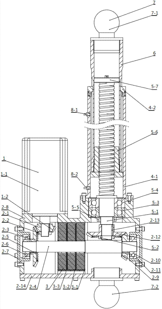
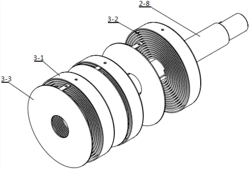
[0028] An energy storage electric cylinder is composed of a motor assembly (1), a reducer (2), a coil spring assembly (3), a cylinder assembly (4), a screw subassembly (5), a push rod (6), and an installation Component (7) and limit switch (8) are formed. It is characterized in that: the motor assembly (1) is installed on the upper end of the reducer (2) through screws, and the helical gear 1 (2-1) is installed on the output shaft of the motor (1-1), and the helical gear 1 (2-1) is installed on the output shaft of the motor (1-1). 1) Process the keyway on the shaft hole of the motor (1-1) and the output shaft of the motor (1-1), and restrict the helical gear 1 (2-1) and The output shaft of the motor (1-1) rotates relative to each other. The end of the output shaft of the motor (1-1) is processed with external threads, and the upper end surface of the helical gear 1 (2-1) is tightened by tightening the lock nut 1 (2-2). Close to the stepped surface on the output shaft of the m...


PUM


Abstract

The invention discloses an energy storage electric cylinder. The energy storage electric cylinder is composed of a motor assembly, a speed reducer, a coil spring assembly, a screw pair assembly, a cylinder body assembly, a push rod, an installation assembly and limit switches. The motor assembly is installed at the input end of the speed reducer, and the screw pair assembly is installed at the output end of the speed reducer. A feed screw nut and the push rod are fixed into a whole and further slide in the cylinder body assembly together. The cylinder body assembly is installed at the output end of the speed reducer. A ball 1 is installed at the top end of the push rod, and a ball 2 is installed on a speed reducer bottom cover. The limit switch 1 is installed above the cylinder body assembly, and the limit switch 2 is installed below the cylinder body assembly. The coil spring assembly is installed on a transmission shaft of the speed reducer and used for storing or releasing energy along with rotation of the transmission shaft. According to the energy storage electric cylinder, gravitational potential energy of a conveyed object or kinetic energy of a motor in the idle stroke is converted into elastic potential energy of a coil spring to be stored, the stored energy is released in the other stroke, electric energy consumed by the motor can be greatly lowered, and carrying capacity of the motor can be improved obviously.

Description

technical field [0001] The invention relates to an energy storage electric cylinder, in particular to an electric cylinder equipped with a coil spring mechanism and capable of storing energy, which belongs to the field of mechanical transmission. Background technique [0002] With the rapid development of industrial automation, the application of electric cylinders is becoming more and more extensive. The electric cylinder is an actuator that can convert the rotational motion of the motor into the linear motion of the push rod. It is a modular product integrating the motor and the screw. It is currently widely used in robot arms and joints, simulated aircraft, lifting platform and other devices. Compared with hydraulic and pneumatic drive equipment, electric cylinders have the characteristics of environmental protection and energy saving, easy control, high precision and low maintenance cost. [0003] Chinese patent CN 113593A discloses an electric cylinder that reduces vi...

Claims


Application Information

Patent Timeline
Patent Type & Authority Applications(China)
IPC IPC(8): F03G1/00H02K7/116
CPCF03G1/00H02K7/116
Inventor 丁高鹏王斌
Owner NANJING TONYS AUTOMATION TECH CO LTD
Learn More