Multichannel speed-control liquid nitrogen buffer fluid infusion device

A liquid replenishment device and multi-channel technology, which is applied in the pipeline system, gas/liquid distribution and storage, mechanical equipment, etc., can solve the problems of reducing the pressure of liquid nitrogen in the buffer tank, uncontrollable, unsustainable and stable output, etc., to reduce liquid nitrogen. Nitrogen loss, reduced heat exchange effects

Inactive Publication Date: 2017-10-24
HUAZHONG UNIV OF SCI & TECH
View PDF17 Cites 4 Cited by
  • Summary
  • Abstract
  • Description
  • Claims
  • Application Information

AI Technical Summary

Problems solved by technology

[0004] In view of the above defects or improvement needs of the prior art, the present invention provides a multi-channel speed-controlled liquid nitrogen buffer device, the purpose of which is to buffer high-speed and high-pressure liquid nitrogen by setting buffer baffles in the buffer tank; An exhaust and pressure-reducing port is set on the top of the buffer tank to reduce the pressure of liquid nitrogen in the buffer tank, and by setting multiple liquid outlet pipes, the multi-channel liquid nitrogen speed control output is realized, thereby solving the problem of the existing technology for extremely low temperature liquid nitrogen. Nitrogen lacks mature buffer devices and methods, and most of them rely on manual operation. When flowing directly from a large Dewar tank, the flow rate is violent and the flow rate is uncontrollable, and the technical problem of unable to continuously and stably output liquid nitrogen

Method used


Image

  • Multichannel speed-control liquid nitrogen buffer fluid infusion device

Examples


Embodiment Construction

[0027] In order to make the object, technical solution and advantages of the present invention clearer, the present invention will be further described in detail below in conjunction with the accompanying drawings and embodiments. It should be understood that the specific embodiments described here are only used to explain the present invention, not to limit the present invention. In addition, the technical features involved in the various embodiments of the present invention described below can be combined with each other as long as they do not constitute a conflict with each other.

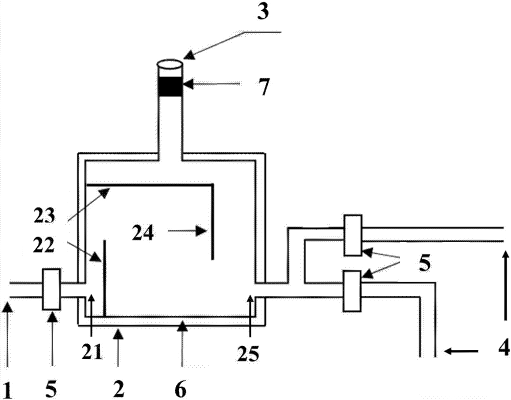
[0028] The present invention provides a multi-channel speed-controlled liquid nitrogen buffer replenishment device, which includes a buffer tank 2 and liquid inlet pipes and liquid outlet pipes respectively arranged at the bottom of both sides of the buffer tank 2, wherein:

[0029] One end of the liquid inlet pipe is provided with a liquid inlet 1 for introducing liquid nitrogen into the buffer...


PUM


Abstract

The invention relates to the technical field of low temperatures, in particular to a multichannel speed-control liquid nitrogen buffer fluid infusion device. The device comprises a buffer tank, a fluid inlet pipe and a plurality of fluid outlet pipes, wherein the fluid inlet pipe and the fluid outlet pipes are respectively arranged at the bottoms of two sides of the buffer tank; a fluid inlet is formed in one end of the fluid inlet pipe and is used for importing liquid nitrogen to the buffer tank; the other end of the fluid inlet pipe is connected with a buffer tank inlet; a buffer baffle plate is arranged in the buffer tank and is used for reducing the flow speed of the high-speed liquid nitrogen; an exhaust and pressure reduction opening is formed in the top end of the buffer tank, the opening size of the exhaust and pressure reduction opening is adjustable; the exhaust and pressure reduction opening is used for controlling the flow speed of the liquid nitrogen; fluid outlets are formed in one ends of the fluid outlet pipes and are used for outputting liquid nitrogen; the other ends of the fluid outlet pipes are connected with a buffer tank outlet; and the fluid outlet pipes are used for realizing multichannel speed-control output of liquid nitrogen. According to the device, the technical problems that liquid nitrogen at extremely low temperatures lacks of mature buffer device and method, manual operations are required, the liquid nitrogen flows acutely when directly flowing out from large-scale Dewar tanks, the flow speed is uncontrollable and the liquid nitrogen cannot be continuously and stably output are solved.

Description

technical field [0001] The invention relates to the field of cryogenic technology, and more specifically, relates to a multi-channel speed-controlled liquid nitrogen buffer replenishment device. Background technique [0002] Under normal pressure, the temperature of liquid nitrogen is -196°C, which is a refrigerant. Due to its low temperature, strong stability, non-toxic and non-polluting characteristics, liquid nitrogen is widely used in many fields such as industry, medical treatment, and biology, such as: rapidly freezing food, storing and freezing biological tissues, excision of diseased tissues in medical experiments, and cryotherapy wait. Liquid nitrogen is generally stored in a large Dewar tank with a capacity of 100 liters. When using liquid nitrogen, it is necessary to drain the liquid nitrogen in the Dewar tank to the target container to be used. Due to the high internal pressure of the large Dewar tank, when liquid nitrogen flows out of it, it has the characteri...

Claims


Application Information

Patent Timeline
Patent Type & Authority Applications(China)
IPC IPC(8): F17D1/20F17D1/08F17D3/01
CPCF17D1/082F17D1/20F17D3/01
Inventor 袁菁骆清铭秦少游
Owner HUAZHONG UNIV OF SCI & TECH
Why Eureka
Try Eureka