Carriage window air-flow state tracking device and experimental method

A carriage and state technology, applied in the direction of measuring devices, aerodynamic tests, instruments, etc., can solve the problem of inability to determine the flow state at the window and inside the carriage, the inability to judge the influence of fire spread in the wind field, and the neglect of the influence of local backflow due to air disturbance, etc. problem, to achieve the effect of reusable experimental efficiency, stable and adjustable flue gas flow, and simple debugging

Pending Publication Date: 2017-10-24
TIANJIN FIRE RES INST
View PDF9 Cites 10 Cited by
  • Summary
  • Abstract
  • Description
  • Claims
  • Application Information

AI Technical Summary

Problems solved by technology

At present, the air volume measurement in the fire research in the compartment mostly relies on the method of arranging the anemometer at the designated position at the window. The point flow field is used instead of the flow field of the entire surface to estimate the air intake volume, and there are large calculation errors. First, During the test, it is impossible to determine the flow state at the window and inside the compartment, so the local backflow influence factors caused by air disturbance are often ignored
The second is that due to the real-time changes in the direction of the complex wind field of the moving car body, it is difficult to measure and measure these complex airflow states by relying on the existing anemometer
Third, after the anemometer is set, it can only measure the wind speed in the specified direction, but the air actually flowing at the window often has a certain angle with the window, and the test results of the anemometer cannot accurately describe the actual airflow state
In addition, the flow state of the air in the interior of the car cannot be known, let alone the influence of the wind field on the spread of the fire in the event of a fire.

Method used


Image

  • Carriage window air-flow state tracking device and experimental method
  • Carriage window air-flow state tracking device and experimental method

Examples


Embodiment Construction

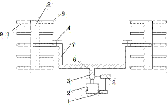
[0028] Such as figure 1 As shown in the figure, an airflow state tracing device at the window of a carriage includes a smoke generator 1, a smoke storage tank 2, a fan 3, a flow regulating valve 4, a power supply 5, and also includes a main pipe 6, a branch pipe 7, a buffer pipe 8, Release tube 9.

[0029] The buffer pipe 8, the release pipe 9 and the flow regulating valve 4 constitute a smoke release group pipe. On both sides of the buffer pipe 8 blocked at both ends, there are symmetrically connected pairs of release pipes 9, and the outside of each release pipe 9 is In the blocked state, on the bottom of several pairs of release pipes 9, several smoke release holes 9-1 are arranged vertically downward at intervals, and a flow regulating valve 4 is provided on the buffer pipe 8 on the middle side of the buffer pipe 8. The output port of the flow regulating valve 4 communicates with the buffer pipe 8 and several pairs of release pipes 9;

[0030] Connect the smoke storage t...


PUM


Abstract

The invention relates to a carriage window air-flow state tracking device and experimental method. The method comprises the steps: a fan is turned on to circulate the air in a pipeline, a flue gas generator is turned on, the flue gas is released through a main pipe, a branch pipe, a flow regulating value, a buffer tube, a release tube and a releasing hole to carriage window, and the rotating speed of the fan is regulated to control the flow, so that the trace of the flue gas in the carriage is clearly visible; a camera shoots the released flue gas and saved the image to a computer, real-time flow state of the air in the carriage is directly displayed, and the wind direction at the window is judged; wind speed data collected by a wind-velocity indicator is recorded by a data collector and introduced into the computer, the entrance time and speed curves are drawn by the data collector, the ventilation volume at the carriage window is calculated hereby, so that the data is provided for wind field simulation and fire oxygen consumption calculation of following fire space, and the device and the method are important for fire state judgment in fire-fighting study.

Description

technical field [0001] The invention belongs to the technical field of air flow field testing, and in particular relates to an air flow state tracing device and an experimental method at the window of a carriage, mainly used for measuring the air flow state at the window and the air flow state inside the locomotive when the diesel locomotive is running. . Background technique [0002] In fire science research, it is often necessary to measure the air flow state at the window of the car, such as the measurement of the air flow state at the window when the diesel locomotive is running, the measurement of the air flow state inside the locomotive, etc. As one of the three elements of fire occurrence, air has a great influence on the development of fire, fire state, and the timing of fire fighting. It is the focus of analysis and testing in fire research. At present, the air volume measurement in the fire research in the compartment mostly relies on the method of arranging the a...

Claims


Application Information

Patent Timeline
Patent Type & Authority Applications(China)
IPC IPC(8): G01M9/06
CPCG01M9/06
Inventor 赵力增纪超陈涛夏建军刘晅亚
Owner TIANJIN FIRE RES INST
Why Eureka
Try Eureka