
Method for obtaining target distance and target intensity realized on the basis of 4D imaging photon counting laser radar system

A technology of photon counting and laser radar, which is applied in radio wave measurement system, re-radiation of electromagnetic waves, utilization of re-radiation, etc., can solve the problems of long time consumption, large amount of calculation, and low accuracy of intensity calculation, and achieve intensity calculation The effect of improving accuracy, improving efficiency, and simplifying the process of solving

Active Publication Date: 2017-10-24
HARBIN INST OF TECH
View PDF2 Cites 9 Cited by
  • Summary
  • Abstract
  • Description
  • Claims
  • Application Information

AI Technical Summary

Problems solved by technology

[0005] The purpose of the present invention is to solve the problems of long time consumption and low accuracy of calculating the intensity caused by the large calculation amount of distance calculation in the existing methods for acquiring target distance and target intensity. The present invention provides a 4D imaging photon counting laser radar The acquisition method of the target distance and target strength realized by the system

Method used


Image

  • Method for obtaining target distance and target intensity realized on the basis of 4D imaging photon counting laser radar system
  • Method for obtaining target distance and target intensity realized on the basis of 4D imaging photon counting laser radar system
  • Method for obtaining target distance and target intensity realized on the basis of 4D imaging photon counting laser radar system

Examples


specific Embodiment approach 1

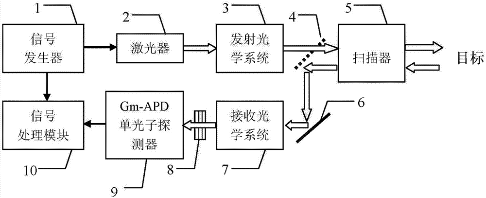
[0023] Specific implementation mode one: see figure 1 Describe this embodiment, the acquisition method of the target distance and target intensity based on the 4D imaging photon counting laser radar system described in this embodiment, the described 4D imaging photon counting laser radar system includes a signal generator 1, a laser 2, a transmitter Optical system 3, one-way reflector 4, scanner 5, total reflection mirror 6, receiving optical system 7, narrowband filter 8, Gm-APD single photon detector 9, signal processing module 10;

[0024] The composite modulated random pulse signal output terminal of the signal generator 1 is connected with the composite signal input terminal of the laser 2 and the composite signal input terminal of the signal processing module 10 at the same time, and the pulse signal output terminal of the laser 2 is connected with the pulse of the emission optical system 3 The signal input terminal is connected, the optical signal output by the transmit...

specific Embodiment approach 2

[0033] Specific implementation mode two: see figure 1 Describe this embodiment. The difference between this embodiment and the acquisition method of the target distance and target intensity based on the 4D imaging photon counting lidar system described in the first embodiment is that the described intensity calculation is realized by the following formula :

[0034] N s =-ln(1-P).

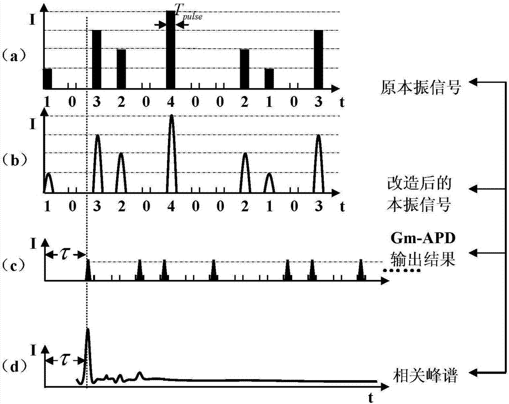
[0035] In this embodiment, if image 3 (a) The local oscillator signal consists of random distribution of pulses with different intensities. We use 1, 2...i...n to represent individual pulses of different intensities, and 1, 2...i...n is called encoding, which represents pulses of different intensities . A detection uses a pulse sequence, including M pulses, and this pulse sequence contains n kinds of pulses with different intensity modulations randomly distributed. Pulses of n different intensities appear with equal probability. Therefore, for a detected pulse sequence, M pulses of various in...

specific Embodiment approach 3

[0040] Specific implementation mode three: see figure 1 This embodiment is described. The difference between this embodiment and the method for acquiring the target distance and target intensity based on the 4D imaging photon counting lidar system described in the first embodiment is that the expression of the radar distance equation is: : R=cτ / 2; wherein, R is the distance value of the target, and c is the speed of light.


PUM


Abstract

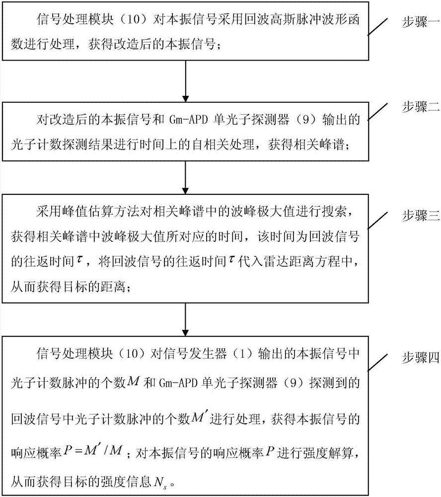
The invention proposes a method for obtaining the target distance and the target intensity realized on the basis of a 4D imaging photon counting laser radar system, which relates to the technical field of a laser radar. The method solves the problems that a currently available method for obtaining the target distance and the target intensity requires a large amount of computation for distance calculation and that the process is time consuming and the computation intensity is low in accuracy. According to the invention, first, a local oscillation signal is transformed so that is possesses the same form as an echo signal, then the reconstructed local oscillation signal and the Gm-APD detection result are subjected to frequency-mixing treatment to obtain a related peak spectrum. On the one hand, the distance information is worked out by searching the position of the peak maximum in the peak spectrum; on the one hand, the intensity information is worked out through processing the number M of photon counting pulses in the local oscillator signal outputted by the signal generator and the number of photon counting pulses M' in the echo signal detected by the Gm-APD single-photon detector. The invention is mainly used to detect the distance and intensity of a target.

Description

technical field [0001] The invention relates to the technical field of laser radar. Background technique [0002] Due to the extremely high response sensitivity and extremely fast photoelectric response speed of Gm-APD, the lidar system based on Gm-APD detector plays an important role in the application field of long-distance and weak signals. However, in various fields of military and civilian applications at present, it is difficult to meet the detection requirements of many complex targets only by the range image. However, due to the logic output of 0 and 1 of the Gm-APD avalanche effect, it can only respond to the arrival time of the signal. , unable to respond to signal strength information. This greatly limits the application prospects of lidar systems based on Gm-APD detectors. In order to solve this problem, people have explored many methods. [0003] Among them, one of the main methods is the 4D imaging photon counting laser radar system with composite modulation...

Claims


Application Information

Patent Timeline
Patent Type & Authority Applications(China)
IPC IPC(8): G01S17/89G01S17/10
CPCG01S17/10G01S17/89
Inventor 张子静赵远孙怿飞王峰
Owner HARBIN INST OF TECH
Learn More