Check patentability & draft patents in minutes with Patsnap Eureka AI!

Continuous reactive power compensation circuit and control method

A technology of power compensation and control method, which is applied in the direction of reactive power adjustment/elimination/compensation, reactive power compensation, circuit device, etc., can solve problems such as the inability to realize reactive power control of the power grid, and improve the effect of dynamic reactive power control, circuit Simple structure, easy to control the effect

Active Publication Date: 2017-10-24
CHINA THREE GORGES UNIV
View PDF4 Cites 5 Cited by
  • Summary
  • Abstract
  • Description
  • Claims
  • Application Information

AI Technical Summary

Problems solved by technology

Combining the technical status of the current reactive power compensation equipment and the actual characteristics of the reactive power demand of the power grid, the existing technology cannot meet the needs of reactive power control of the power grid in different time dimensions

Method used


Image

  • Continuous reactive power compensation circuit and control method
  • Continuous reactive power compensation circuit and control method
  • Continuous reactive power compensation circuit and control method

Examples


Embodiment Construction

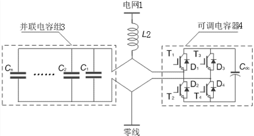
[0026] Such as figure 1 As shown, in the embodiment of the present invention: a continuous reactive power compensation circuit, including a grid 1, a reactor L2, a parallel capacitor bank 3 and an adjustable capacitor 4; one end of the reactor L2 is connected to the grid 1, and the other end is connected to the parallel capacitor Group 3 is connected to adjustable capacitor 4; parallel capacitor group 3 is composed of C 1 、C 2 …C n composed of AC capacitors, C 1 、C 2 …C n AC capacitors are connected in parallel with each other; the adjustable capacitor 4 consists of T 1 , T 2 , T 3 , T 4 , Diode D 1 、D 2 、D 3 、D 4 and a DC capacitor C dc Composition, T 1 , T 2 , T 3 , T 4 The collectors of the diodes D 1 、D 2 、D 3 、D 4 connected to the cathode, T 1 , T 2 , T 3 , T 4 The emitters are connected to the diode D 1 、D 2 、D 3 、D 4 connected to the anode of T 1 with D 1 , T 2 with D 2 , T 3 with D 3 , T 4 with D 4 Form four groups of switch modules...


PUM


Abstract

The invention discloses a continuous reactive power compensation circuit. The continuous reactive power compensation circuit comprises a power grid, a reactor L, a parallel connection capacitor group, and an adjustable capacitor. One end of the reactor L is connected with the power grid, and the other end of the reactor L is connected with the parallel connection capacitor group and the adjustable capacitor. The parallel connection capacitor group comprises n AC capacitors, which are parallely connected together. The adjustable capacitor is constituted by four IGBT (T1-T4), four diodes (D1-D4), and a direct current capacitor C<dc>. By monitoring and analyzing the reactive power of the power grid, reactive compensation quantities in different time periods are decomposed into constant quantity parts and fluctuating quantity parts, and the parallel connection capacitor group is used to compensate the constant quantity parts, and the adjustable capacitor is used to compensate the fluctuating quantity parts. The continuous reactive power compensation circuit has advantages of high control precision, fast responding speed, and abilities of facilitating expansion, improving compensation capacity, and improving comprehensive compensation capability of device.

Description

technical field [0001] The invention relates to the technical field of electrical control, in particular to a continuous reactive power compensation circuit and a control method. Background technique [0002] Reactive power compensation is the main way to control the reactive power balance of the power grid. It is also the key equipment to ensure the safe, stable and reliable operation of the power grid. It mainly includes: static var compensator (SVC) and static var generator (STATCOM). At present, SVC is generally controlled by thyristors, including thyristor switched capacitors (TSC) and thyristor controlled reactors (TCR). However, the compensation accuracy is low, the response speed is slow, and the harmonic content is high; STATCOM is generally controlled by an insulated gate bipolar transistor (IGBT), which has a good compensation effect and low current harmonic content, but the compensation capacity is not high and the control is more complicated. In practice, the d...

Claims


Application Information

Patent Timeline
IPC IPC(8): H02J3/18
CPCH02J3/1842Y02E40/30
Inventor 魏业文曹斌刘国特王辉程江洲
Owner CHINA THREE GORGES UNIV
Features
  • R&D
  • Intellectual Property
  • Life Sciences
  • Materials
  • Tech Scout
  • Unparalleled Data Quality
  • Higher Quality Content
  • 60% Fewer Hallucinations
Learn More