Stationary contact point automatic riveting machine

A technology of static contact and riveting press, which is applied in the direction of feeding device, positioning device, storage device, etc., can solve the problems of low efficiency, hidden danger, and inability to realize static contact, and achieves the improvement of production efficiency and simple structure. Effect

Inactive Publication Date: 2017-10-27
苏州明雪电子有限公司
View PDF11 Cites 4 Cited by
  • Summary
  • Abstract
  • Description
  • Claims
  • Application Information

AI Technical Summary

Problems solved by technology

At present, most of the traditional small riveting presses generally adopt the manual loading method, that is, manually place the static contact piece and the static contact point on the designated station. This feeding method is inefficient and has potential safety hazards; The medium and large riveting presses on the market mainly use automatic feeding equipment, usually through the vibration of the vibrating plate, which greatly improves the efficiency of feeding, but this feeding method also has certain defects. : If the accuracy of the feeding position of the static contact piece and the static contact piece cannot be realized, the automatic insertion of the static contact piece into the static contact piece cannot be realized, etc.

Method used


Image

  • Stationary contact point automatic riveting machine
  • Stationary contact point automatic riveting machine
  • Stationary contact point automatic riveting machine

Examples


Embodiment Construction

[0030] The following will clearly and completely describe the technical solutions in the embodiments of the present invention with reference to the accompanying drawings in the embodiments of the present invention. Obviously, the described embodiments are only some, not all, embodiments of the present invention. Based on the embodiments of the present invention, all other embodiments obtained by persons of ordinary skill in the art without creative efforts fall within the protection scope of the present invention.

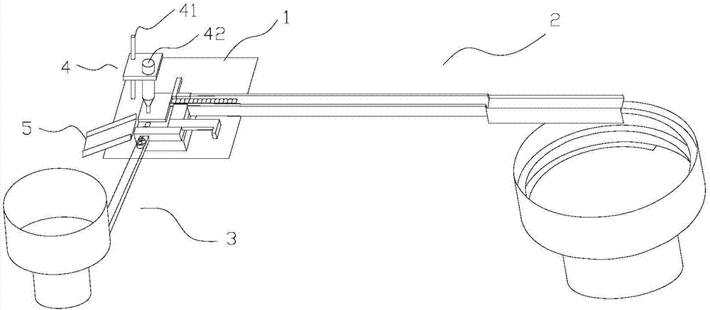
[0031] refer to figure 1 As shown, the static contact automatic riveting machine of the present invention includes a workbench 1 and a static contact sheet feeding mechanism 2, a static contact feeding mechanism 3 and a riveting mechanism 4 arranged on the workbench 1;

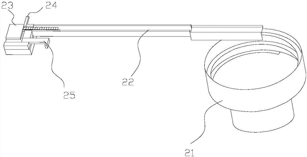
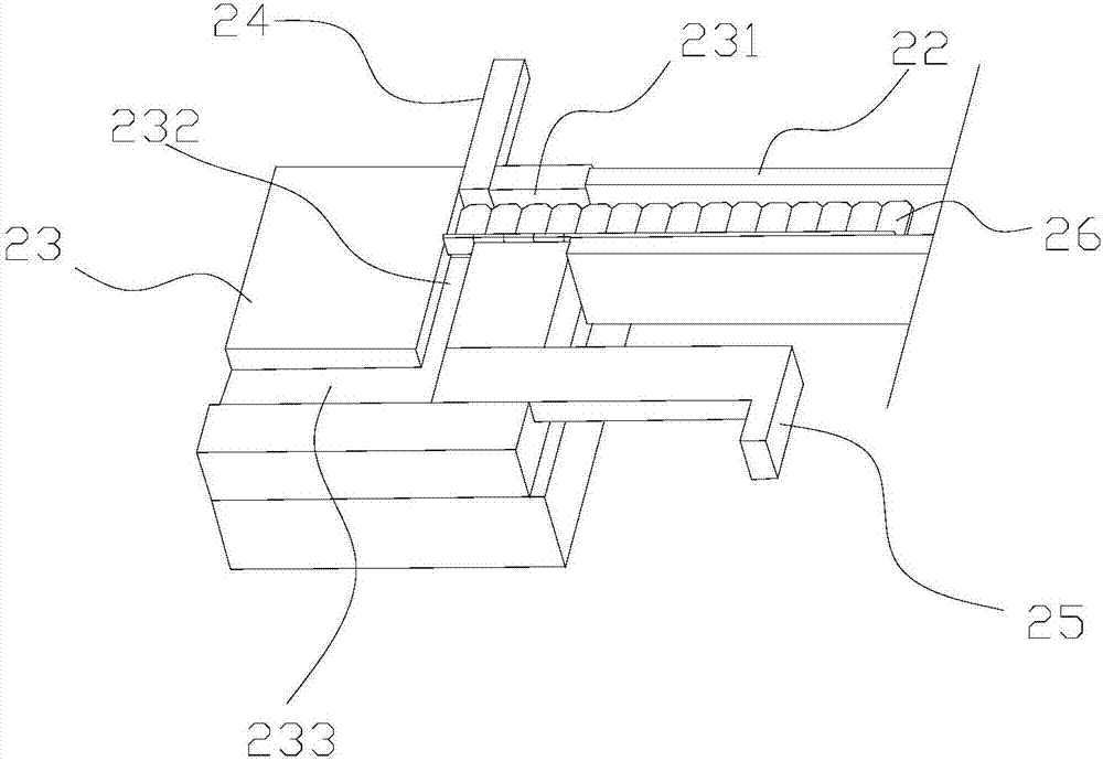
[0032] like Figure 2-3 As shown, the static contact feeding mechanism 2 includes a first vibrating plate 21, a first feeding track 22, a shaping positioning block 23, a first pushing block 24 and...


PUM


Abstract

The invention discloses a stationary contact point automatic riveting machine. The stationary contact point automatic riveting machine comprises a workbench, a stationary wafer feeding mechanism, a stationary contact point feeding mechanism and a riveting head, and the stationary wafer feeding mechanism, the stationary contact point feeding mechanism and the riveting head are arranged on the workbench; the stationary wafer feeding mechanism comprises a first vibration disc, a first feeding track, a shaping locating block, a first push block and a second push block; the stationary contact point feeding mechanism comprises a second vibration disc, a second feeding track, a top pillar, and a bevel push block; the riveting head is fixed to the workbench through a mounting frame. The stationary contact point automatic riveting machine is simple in structure, automatic feeding and riveting of stationary contact points and stationary wafers can be achieved, and the working efficiency of riveting is improved.

Description

technical field [0001] The invention relates to the field of riveting presses, in particular to an automatic riveting press for riveting static contacts in cooling fins. Background technique [0002] The heat sink is a device for cooling the heat-prone electronic components in electrical appliances. It is mostly made of aluminum alloy, brass or bronze into plates, sheets, and multi-sheets. For example, the CPU central processing unit in a computer needs to use a large Heat sinks, power tubes in TVs, line tubes, and power amplifier tubes in power amplifiers all use heat sinks. Generally, the heat sink should be coated with a layer of heat-conducting silicone grease on the contact surface between the electronic components and the heat sink during use, so that the heat emitted by the components can be more effectively transferred to the heat sink, and then dissipated into the surrounding air through the heat sink. [0003] The static contact piece and the static contact point ...

Claims


Application Information

Patent Timeline
Patent Type & Authority Applications(China)
IPC IPC(8): B21D43/13B21D39/00B21D53/02
Inventor 张夏
Owner 苏州明雪电子有限公司
Why Eureka
Try Eureka