

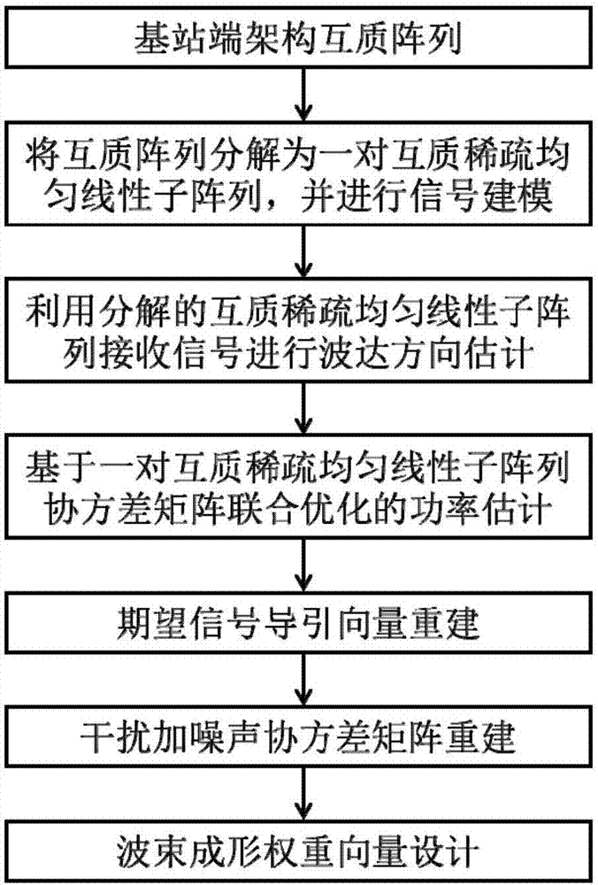
Adaptive beam forming method based on coprime array
An adaptive beam and array technology, applied in the field of signal processing, can solve problems such as degradation, inability to fully utilize the properties and output performance of co-prime arrays
- Summary
- Abstract
- Description
- Claims
- Application Information
AI Technical Summary
Problems solved by technology
Method used
Image

Examples
example 1
[0103] Simulation example 1: The spatial power spectrum corresponding to the direction of arrival and power value estimated in the present invention is compared with the spatial power spectrum obtained by the Capon method using a coprime array and a uniform linear array of 10 antenna physical array elements. Figure 4 shown. The signal-to-noise ratio of the desired signal is 20dB, and the number of sampling snapshots is L=30. It can be seen that the method proposed in the present invention can effectively estimate the direction of arrival and power value of the desired signal and each interference signal, and the power estimation effect is better than the Capon method. Although there are two additional estimated signal sources, which are caused by the unknown number of interference sources in advance, their power estimates are extremely low, and they only occupy a very small proportion in the process of interference-plus-noise covariance matrix reconstruction. The perturbatio...
example 2
[0104] Simulation example 2: The performance comparison between the output signal-to-interference-noise ratio of the method proposed in the present invention and the existing adaptive beamforming method in the case of random direction error of the signal is as follows Figure 5 and Figure 6 As shown, the comparison methods include: sampling covariance matrix inversion method, diagonal loading method, subspace-based method, worst-case performance optimization method, and covariance matrix reconstruction method. It is assumed that both the desired signal and the interference signal have a random error that satisfies the uniform distribution of [-4°, 4°], that is, the direction of arrival of the desired signal is randomly generated within the range of [1°, 9°], and the waves of the two interference signals Arrival directions are randomly generated in the ranges of [-54°, -46°] and [-24°, -16°] respectively. The angle domain range of the desired signal is Φ=[θ s -5°, θ s +5°...
PUM
 Abstract
Description
Claims
Application Information