A kind of ptc liquid heater and its heating control method

A liquid heater and heating control technology, applied in heating/cooling equipment, vehicle parts, transportation and packaging, etc., can solve the problem of PTC heating module not working, etc., to reduce the size of the control cabin, the control method is safe, and the comfort is good Effect

Active Publication Date: 2021-03-26
BYD CO LTD
View PDF6 Cites 0 Cited by
  • Summary
  • Abstract
  • Description
  • Claims
  • Application Information

AI Technical Summary

Problems solved by technology

[0007] In order to solve the problem that when the existing PTC liquid heater is heated with full power, the current peak point may appear, so that the protection measures of the whole vehicle are started, the high-voltage circuit is disconnected, and the PTC heating module cannot work, the present invention provides a PTC liquid Heater and heating control method thereof

Method used


Image

  • A kind of ptc liquid heater and its heating control method
  • A kind of ptc liquid heater and its heating control method
  • A kind of ptc liquid heater and its heating control method

Examples


Embodiment 1

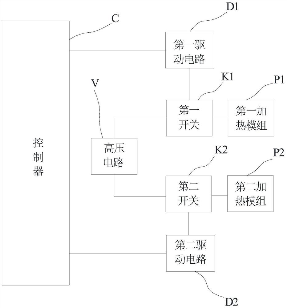
[0060] This example will specifically explain the PTC liquid heater disclosed in the present invention. Such as figure 1 In the block diagram shown, the PTC liquid heater includes a first heating module P1, a second heating module P2, a first switch K1, a second switch, a first drive circuit D1, a second drive circuit D2, a high voltage circuit V and a control Device C;

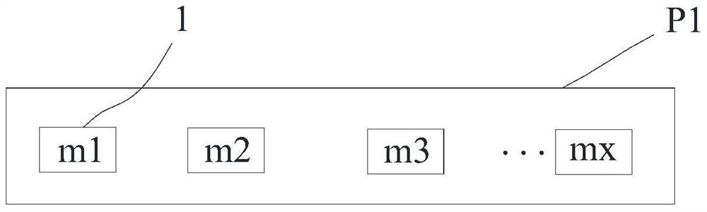
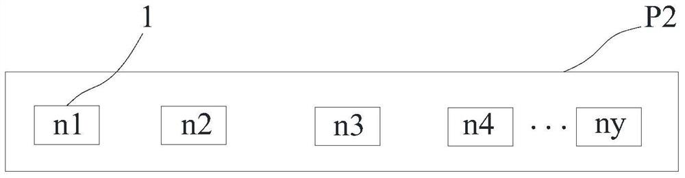
[0061] Among them, such as figure 2 As shown, the first heating module P1 includes x PTC heating modules 1 connected in parallel; for example, m1, m2, m3...mx are marked in the figure with a total of x PTC heating modules 1; as image 3 As shown, the second heating module P2 includes y PTC heating modules 1 connected in parallel, for example, n1, n2, n3, n4...ny are marked n1, n2, n3, n4... ny PTC heating modules 1 in total; wherein, the above-mentioned values ​​of x and y Determined by the heating power of the PTC liquid heater, as a preferred method, in this example, x≤y;

[0062] The above-mentioned P...

Embodiment 2

[0086] This example will specifically explain the heating control method of the above-mentioned PTC liquid heater disclosed in Example 1. The heating control method includes the following steps:

[0087] Such as Figure 7 As shown, the controller C receives the PWM temperature control signal; specifically, as described in Embodiment 1 above, the PWM temperature control signal comes from the ACCU.

[0088] Please understand here that it is a dynamic process for the controller C to receive the PWM temperature control signal. It continuously samples the current temperature T1 and the air outlet speed of the air conditioner within the set period, and obtains the set temperature T0 input by the user in real time. That is, when sending the first logic signal and the second logic signal to the first driving circuit D1 and the second driving circuit D2 later, it is also adjusted dynamically following the above PWM temperature control signal.

[0089] It converts the PWM temperature c...


PUM


Abstract

The invention provides a PTC liquid heater and a heating control method thereof to solve the problem that a PTC heating module cannot work due to the fact that a current peak point can appear when an existing PTC liquid heater carries out heating and protective measures are started by a whole vehicle. The PTC liquid heater comprises a first heating module, a second heating module, a first switch, a second switch, a first drive circuit, a second drive circuit, a high-voltage circuit and a controller, wherein the first heating module comprises x PTC heating modules which are connected in parallel; the second heating module comprises y PTC heating modules which are connected in parallel; and the controller transmits default delay time t to a first logic signal of the first drive circuit and a second logic signal of the second drive circuit. According to the PTC liquid heater, the current impact can be reduced by adopting two-gear grouping and PWM control modes, the current peak point is effectively prevented and the control mode is safer.

Description

technical field [0001] The invention relates to an air-conditioning and heating system of a new energy vehicle, in particular to the field of a PTC liquid heater therein. Background technique [0002] With the rapid development of new energy vehicles, especially the development of high-voltage pure electric vehicles, the air-conditioning and heating scheme of the whole vehicle has changed accordingly. Considering its safety, stability and comfort, the current trend is to use high-voltage PTC liquid heaters, which have met Heating, defrosting, defogging and other needs. [0003] The existing PTC liquid heater mainly includes several heating modules, several control switches (usually IGBT), several driving circuits, high-voltage circuits and controllers; the heating module includes several PTC heating modules; the control switches are connected to the Between the high-voltage circuit and the heating module, the control terminal of the control switch is connected to the drive ...

Claims


Application Information

Patent Timeline
Patent Type & Authority Patents(China)
IPC IPC(8): B60H1/22
CPCB60H1/2218
Inventor 陈永良陈小冬杨峰张达
Owner BYD CO LTD
Why Eureka
Try Eureka