
CrB2 coating layer with high hardness and corrosion resistance on surface of stainless steel substrate and preparation method thereof

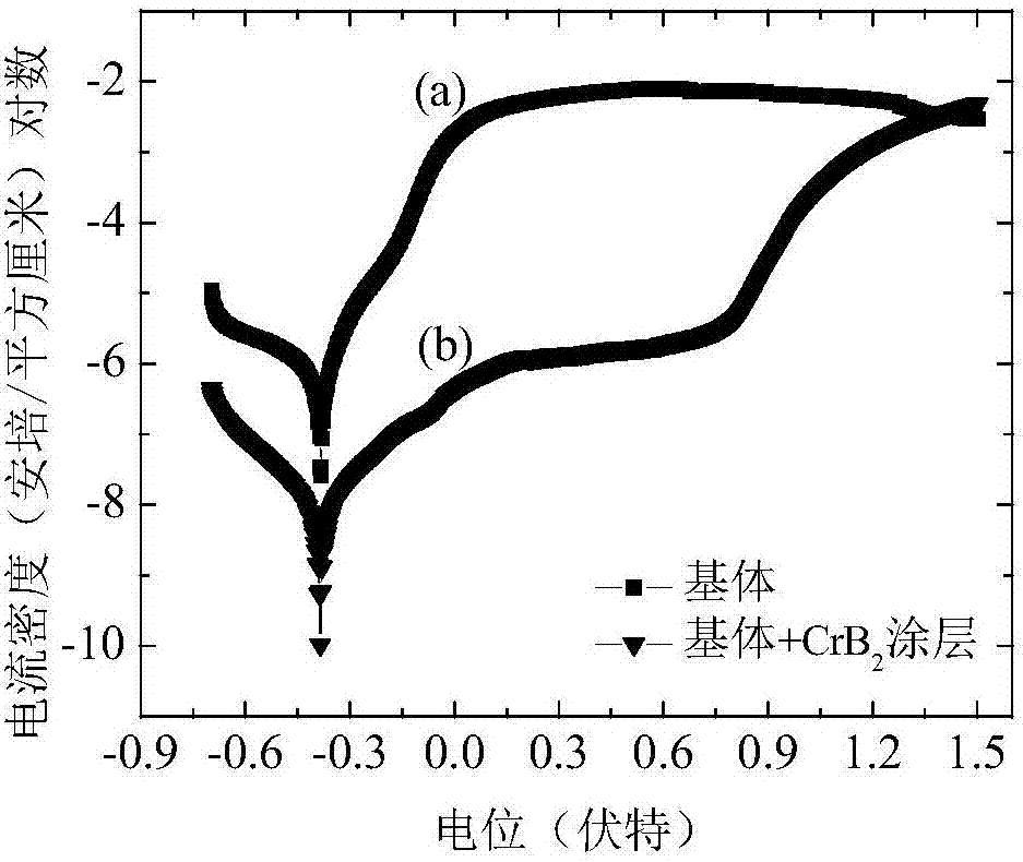
A substrate surface, stainless steel technology, applied in metal material coating process, coating, ion implantation plating and other directions, can solve the problem of narrow phase interval, achieve dense structure, excellent wear and corrosion resistance, high hardness and the effect of compaction

Inactive Publication Date: 2017-11-03
NINGBO INST OF MATERIALS TECH & ENG CHINESE ACADEMY OF SCI
View PDF2 Cites 6 Cited by
  • Summary
  • Abstract
  • Description
  • Claims
  • Application Information

AI Technical Summary

Problems solved by technology

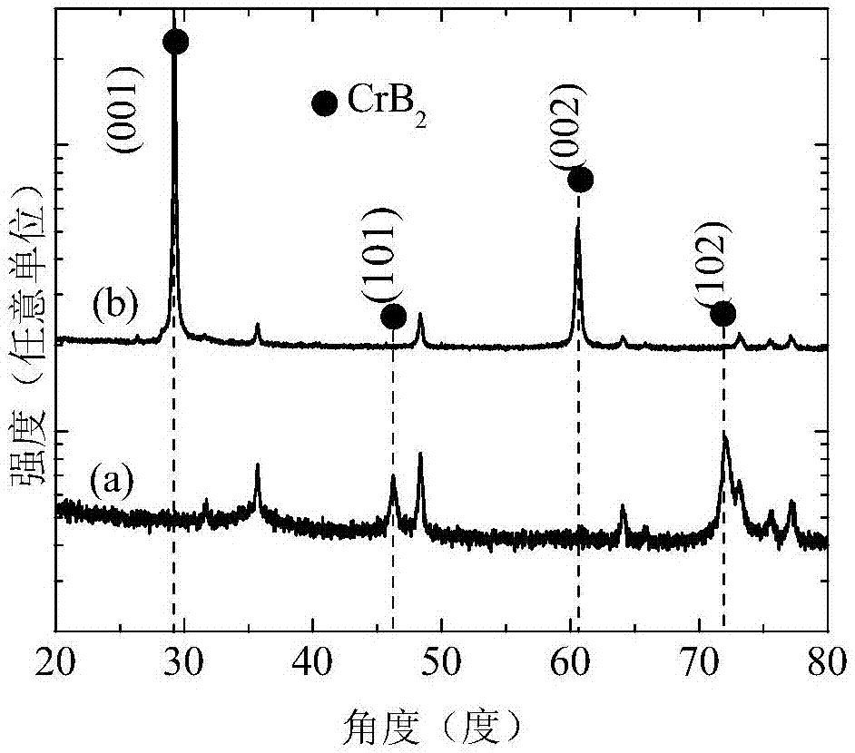
Among them, hexagonal CrB 2 High hardness, strong corrosion resistance, but narrow phase interval, CrB 2 Coating preparation is a big challenge

Method used


Image

  • CrB2 coating layer with high hardness and corrosion resistance on surface of stainless steel substrate and preparation method thereof
  • CrB2 coating layer with high hardness and corrosion resistance on surface of stainless steel substrate and preparation method thereof

Examples


Embodiment 1

[0024] In this embodiment, the substrate is AISI 316L stainless steel. The protective coating on the surface of the substrate is CrB 2 The phase is the main phase structure.

[0025] The preparation method of above-mentioned protective coating is as follows:

[0026] The surface of the substrate is polished, decontaminated, ultrasonically cleaned with acetone and alcohol, and then placed in a vacuum chamber, and the coating is deposited by high-power pulse magnetron sputtering. Specifically, the substrate is facing the sputtering source in the vacuum chamber, and the target The base distance is 8cm; the Cr-B composite target is selected, in which the atomic ratio of Cr to B is 1:2, and argon gas is introduced as the working gas, and the flow rate of argon gas is 50 sccm; the cavity temperature is adjusted to 300°C, and the cavity pressure is 0.28Pa; high-power pulse sputtering power supply parameters are DC 1.8A, pulse voltage 650V, frequency 200Hz, pulse width 200μs; substr...

Embodiment 2

[0033] In this embodiment, the substrate is AISI 316L stainless steel. The protective coating on the surface of the substrate is CrB 2 The phase is the main phase structure.

[0034] The CrB on the surface of the substrate was prepared by high-power pulse magnetron sputtering method and DC magnetron sputtering method respectively. 2 coating, as follows:

[0035]The surface of the substrate was polished, decontaminated, ultrasonically cleaned with acetone and alcohol, and then placed in a vacuum chamber. The protective coating was deposited by high-power pulse magnetron sputtering and DC magnetron sputtering, specifically:

[0036] During the deposition process, the substrate is facing the sputtering source in the vacuum chamber, and the base distance of the target is 8cm; a Cr-B composite target is selected, in which the atomic ratio of Cr to B is 1:2, and argon gas is introduced as the working gas, and the flow rate of the argon gas is 50sccm; adjust the cavity temperature...


PUM

PropertyMeasurementUnit
Corrosion potentialaaaaaaaaaa

Abstract

The invention discloses a CrB2 coating layer with high hardness and corrosion resistance on the surface of a stainless steel substrate. The coating layer uses a nanometer columnar crystal CrB2 as a main phase structure; and the CrB2 coating layer contains (001) and (002) two types of crystal orientations, wherein (001) is preferentially selected. Experiments prove that the hardness of the coating layer can reach 42-50 GPa; the corrosion speed of matrix is greatly decelerated in simulation of artificial seawater; and the corrosion resistance is excellent. In addition, the invention further provides a method for preparing the coating layer; a high-power pulse magnetron sputtering method is adopted; a Cr-B compound target is used; the Cr-B coating layer with specific phase structure and crystal structure is obtained through adjusting high-power pulse power supply parameters; and the method has such characteristics as high metal ionization rate, low cost, simplicity and easiness in control.

Description

technical field [0001] The invention belongs to the technical field of metal material surface strengthening, and relates to a CrB with high hardness and corrosion resistance on the surface of a stainless steel substrate 2 Coatings and methods for their preparation. Background technique [0002] With the development of marine science and technology and related industries, the development and utilization of marine resources and the construction of marine infrastructure require a large amount of stainless steel materials. Under harsh service conditions such as high humidity, high salinity, etc., the wear and corrosion of stainless steel structural parts are very serious. Traditional stainless steel materials such as 316L, 321, and 17-7PH stainless steel have problems such as uniform corrosion, pitting corrosion, and stress corrosion. At present, the preparation of excellent wear-resistant and corrosion-resistant coating materials on the surface of stainless steel by physical ...

Claims


Application Information

Patent Timeline
IPC IPC(8): C23C14/35C23C14/06
CPCC23C14/35C23C14/067
Inventor 左潇汪爱英柯培玲陈仁德张树参
Owner NINGBO INST OF MATERIALS TECH & ENG CHINESE ACADEMY OF SCI
Learn More