Atomic layer deposition of protective coatings for semiconductor process chamber components
A technology of atomic layer deposition and process chamber, which is applied in semiconductor/solid-state device manufacturing, coating, plating of superimposed layers, etc., and can solve problems such as erosion and adding chamber components
- Summary
- Abstract
- Description
- Claims
- Application Information
AI Technical Summary
Problems solved by technology
Method used
Image
Examples
example 1
[0076] Example 1 - Formation of YO from yttrium oxide and yttrium fluoride monolayers x f y coating
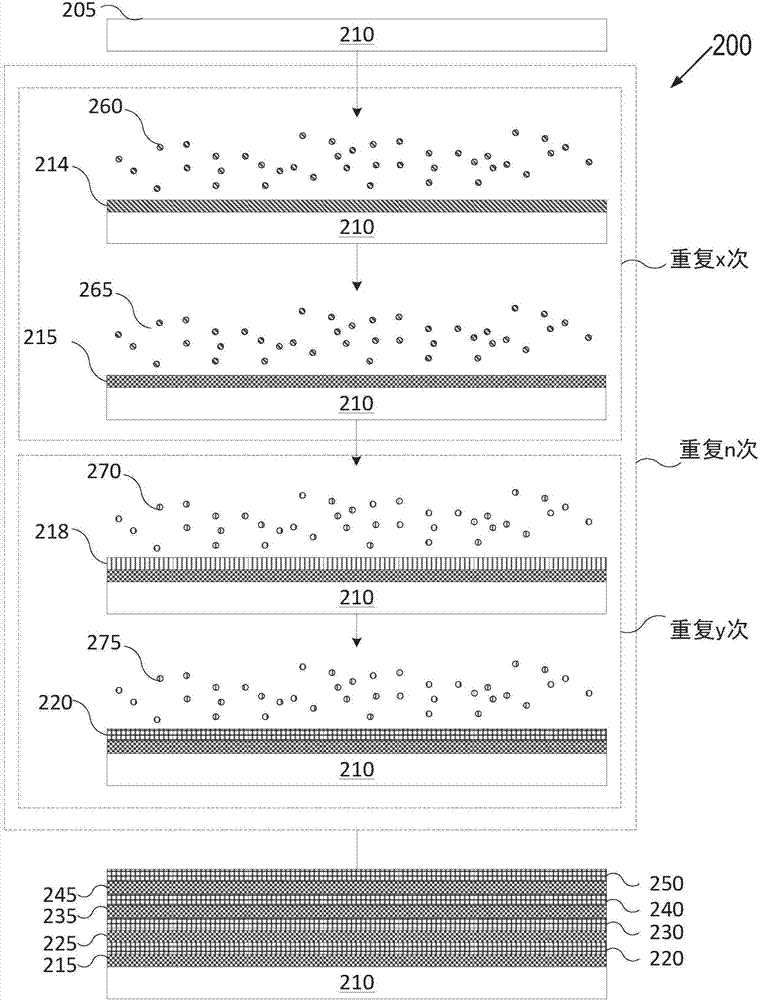
[0077] The first layer can be made of tris(N,N-bis(trimethylsilyl)amide)yttrium(III), tris(cyclopentadienyl)yttrium(III), tris(butylcyclopentadiene) using ALD Alkenyl) yttrium (III), or a precursor of tris (2,2,6,6-tetramethyl-3,5-heptanedionate) yttrium (III) and selected from H 2 O, O 2 , or O 3 A monolayer of yttrium oxide grown from the second precursor. The second layer can be prepared using ALD from the precursors namely tris(2,2,6,6-tetramethyl-3,5-heptanedionate)yttrium(III) and TiF 4 Yttrium fluoride monolayer grown in a single combination. The resulting multi-component coating can include YO x f y , where x and y depend on the number of repetitions of the first and second layers.
example 2
[0078] Example 2 - Formation of YAl from yttria and alumina monolayers x o y coating
[0079] The first layer can be made of tris(N,N-bis(trimethylsilyl)amide)yttrium(III), tris(cyclopentadienyl)yttrium(III), tris(butylcyclopentadiene) using ALD Alkenyl) yttrium (III), or a precursor of tris (2,2,6,6-tetramethyl-3,5-heptanedionate) yttrium (III) and selected from H 2 O, O 2 , or O 3 A monolayer of yttrium oxide grown from the second precursor. The second layer can be made of aluminum diethylethoxide, aluminum tris(ethylmethylamido), aluminum sec-butoxide, aluminum tribromide, aluminum trichloride, triethylaluminum, triisobutylate using ALD. A precursor of aluminum, trimethylaluminum, or tris(diethylamido)aluminum and selected from H 2 O, O 2 , or O 3 A monolayer of alumina grown from the second precursor. The resulting multi-component coating can include YAl x o y , where x and y depend on the number of repetitions of the first and second layers.
[0080] In some e...
example 3
[0084] Example 3 - Formation of YZr from yttria and zirconia monolayers x o y coating
[0085] The first layer can be made of tris(N,N-bis(trimethylsilyl)amide)yttrium(III), tris(cyclopentadienyl)yttrium(III), tris(butylcyclopentadiene) using ALD Alkenyl) yttrium (III), or a precursor of tris (2,2,6,6-tetramethyl-3,5-heptanedionate) yttrium (III) and selected from H 2 O, O 2 , or O 3 A monolayer of yttrium oxide grown from the second precursor. The second layer can be made of zirconium(IV) bromide, zirconium(IV) chloride, zirconium(IV) tert-butoxide, tetrakis(diethylamido)zirconium(IV), tetrakis(dimethylamido)zirconium(IV) using ALD Precursors of zirconium (IV) amido) or tetrakis (ethylmethylamido) zirconium (IV) and selected from H 2 O, O 2 , or O 3 Zirconia monolayer grown from the second precursor. The resulting multi-component coating can include YZr x o y , where x and y depend on the number of repetitions of the first and second layers.
PUM
| Property | Measurement | Unit |
|---|---|---|
| thickness | aaaaa | aaaaa |
| thickness | aaaaa | aaaaa |
Abstract
Description
Claims
Application Information
 - R&D
- Intellectual Property
- Life Sciences
- Materials
- Tech Scout
- Unparalleled Data Quality
- Higher Quality Content
- 60% Fewer Hallucinations
Browse by: Latest US Patents, China's latest patents, Technical Efficacy Thesaurus, Application Domain, Technology Topic, Popular Technical Reports.
© 2025 PatSnap. All rights reserved.Legal|Privacy policy|Modern Slavery Act Transparency Statement|Sitemap|About US| Contact US: help@patsnap.com


