Wheel hub electric motor and wheel hub electric motor system

A technology of in-wheel motor and driving wheel, which is applied to motor vehicles, electromechanical devices, electrical components, etc., can solve the problems of low coding accuracy, difficulty in meeting robots, and low motion control accuracy, and achieve the effect of improving accuracy and coding accuracy.

Pending Publication Date: 2017-11-03
BEIJING EVOLVER ROBOTICS CO LTD
View PDF0 Cites 3 Cited by
  • Summary
  • Abstract
  • Description
  • Claims
  • Application Information

AI Technical Summary

Problems solved by technology

However, in the existing in-wheel motors, the encoding accuracy is low, resulting in low motion control accuracy, and it is difficult to meet the needs of scenarios such as robots that require high intelligent control accuracy.
[0004] For the above-mentioned problem of low coding accuracy of existing in-wheel motors, no effective solution has been proposed

Method used


Image

  • Wheel hub electric motor and wheel hub electric motor system
  • Wheel hub electric motor and wheel hub electric motor system
  • Wheel hub electric motor and wheel hub electric motor system

Examples


Embodiment 1

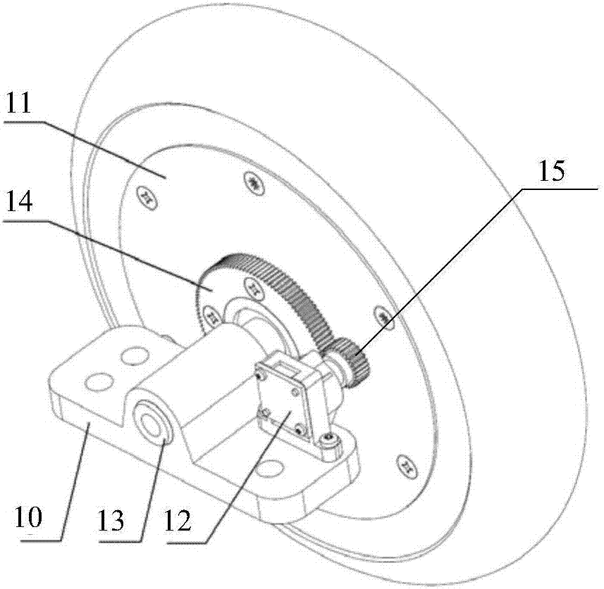
[0030] see figure 1 A structural schematic diagram of an in-wheel motor is shown; the in-wheel motor includes a fixing seat 10, a driving wheel 11 and an encoding module 12;

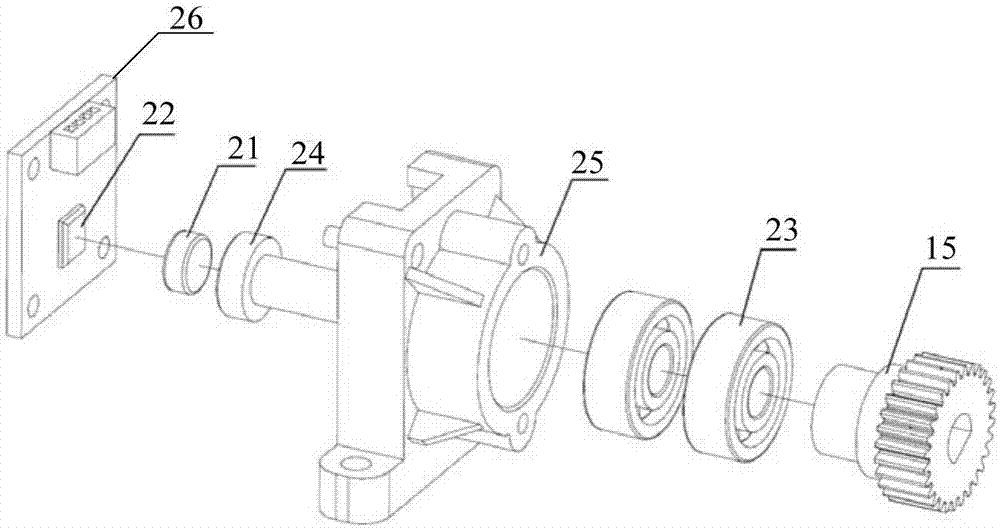
[0031] The driving wheel 11 is connected with the fixed seat 10 through the wheel shaft 13; the coding module 12 is fixedly arranged on the fixed seat 10; the driving wheel 11 is provided with a driving gear 14, and the driving gear 14 rotates synchronously with the driving wheel 11; the driving gear 14 and the coding module 12 The transmission gear 15 in the meshing connection; The diameter of driving gear 14 is greater than the diameter of transmission gear 15;

[0032] When the driving wheel 11 rotates, the driving gear 14 rotates synchronously; the driving gear 14 drives the transmission gear 15 to rotate, so that the encoding module 12 outputs an encoding signal.

[0033] For example, when the transmission gear rotates one revolution, the encoding module can output M encoding signals; since the dia...

Embodiment 2

[0062] Corresponding to the in-wheel motor provided in the first embodiment above, see Figure 5 A structural block diagram of an in-wheel motor system shown; the system includes the above-mentioned in-wheel motor 50, and also includes a central control module 51;

[0063] The central control module 50 is electrically connected to the driving wheel 11 and the encoding module 12 in the in-wheel motor; the central control module 50 is used to control the rotation of the driving wheel 11;

[0064] In an in-wheel motor system provided by an embodiment of the present invention, the driving gear on the driving wheel is meshed with the transmission gear in the encoding module, and the diameter of the driving gear is larger than the diameter of the transmission gear; when the driving wheel rotates, the driving gear drives the transmission gear Rotate to make the encoding module output the encoding signal; in this way, compared with the way that the encoding module is directly connecte...


PUM


Abstract

The invention provides a wheel hub electric motor and a wheel hub electric motor system. The wheel hub electric motor comprises a fixed seat, a driving wheel and a coding module, wherein the driving wheel is connected with the fixed seat via a wheel shaft, the coding module is fixed on the fixed seat, the driving wheel is provided with a driving gear wheel, the driving gear wheel and the driving wheel move synchronously, the driving gear wheel is connected with a transmission gear wheel in the coding module in an engaged manner, and the driving gear wheel is greater than the transmission gear wheel in diameter; when the driving wheel rotates, the driving gear wheel rotates synchronously, the transmission gear wheel is driven to rotate by the driving gear wheel, and therefore coding signals can be output via the coding module. Via the wheel hub electric motor and the wheel hub electric motor system, coding precision of the wheel hub electric motor can be improved, and therefore accuracy of wheel hub electric motor motion control can be improved.

Description

technical field [0001] The invention relates to the technical field of hub motors, in particular to a hub motor and a hub motor system. Background technique [0002] The in-wheel motor technology can also be called the in-wheel motor technology, which is characterized by integrating the power device, transmission device and braking device into the wheel hub, which greatly simplifies the mechanical parts of electric vehicles and other related equipment, and is often used in electric bicycles. , Self-balancing unicycle and other fields. [0003] With the rapid development of robot technology, hub motors are increasingly used in wheeled robots due to their performance advantages. However, in the existing in-wheel motors, the encoding accuracy is low, resulting in low motion control accuracy, and it is difficult to meet the needs of scenarios such as robots that require high intelligent control accuracy. [0004] No effective solution has been proposed for the above-mentioned ...

Claims


Application Information

Patent Timeline
IPC IPC(8): H02K11/21H02K11/215H02K7/10B62M7/12
CPCH02K7/10H02K11/21H02K11/215B62M7/12
Inventor 王刚王兴
Owner BEIJING EVOLVER ROBOTICS CO LTD
Why Eureka
Try Eureka