Conveying device and tuber crop harvester with conveying device

A conveying device and rhizome technology, applied in the field of rhizome crop harvesters, can solve the problems of inability to separate root crops from soil, leaves and other sundries, achieve the convenience of continuous transportation and removal of soil and impurities, improve processing efficiency, The effect of enhanced effect

Pending Publication Date: 2017-11-07
承德万联机械制造有限公司
View PDF9 Cites 5 Cited by
  • Summary
  • Abstract
  • Description
  • Claims
  • Application Information

AI Technical Summary

Problems solved by technology

[0004] The purpose of the present invention is to provide a conveying device to solve the technical problem that the existing conveying device cannot separate root crops from soil, leaves and other s

Method used


Image

  • Conveying device and tuber crop harvester with conveying device
  • Conveying device and tuber crop harvester with conveying device
  • Conveying device and tuber crop harvester with conveying device

Examples


Embodiment 1

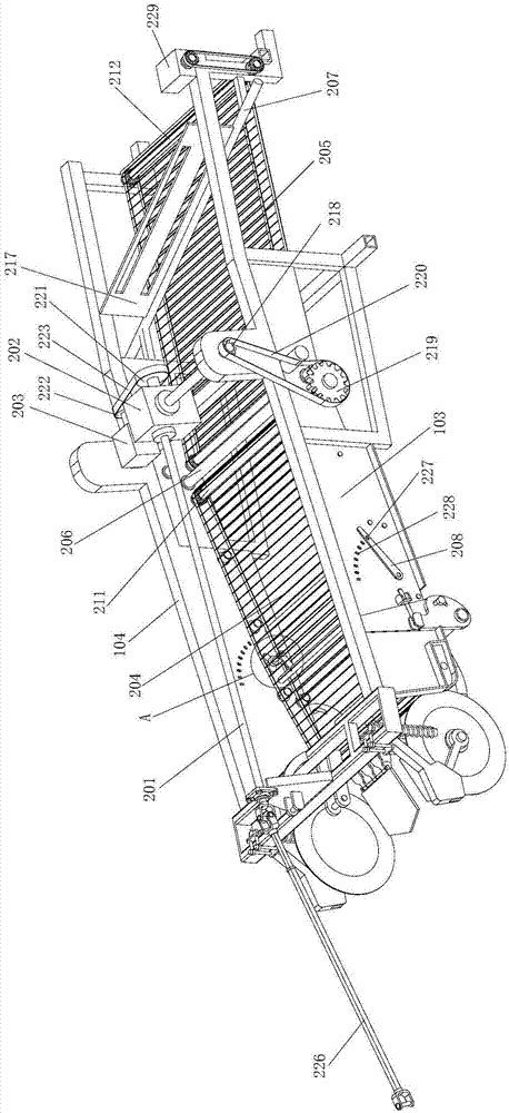
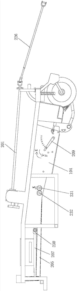
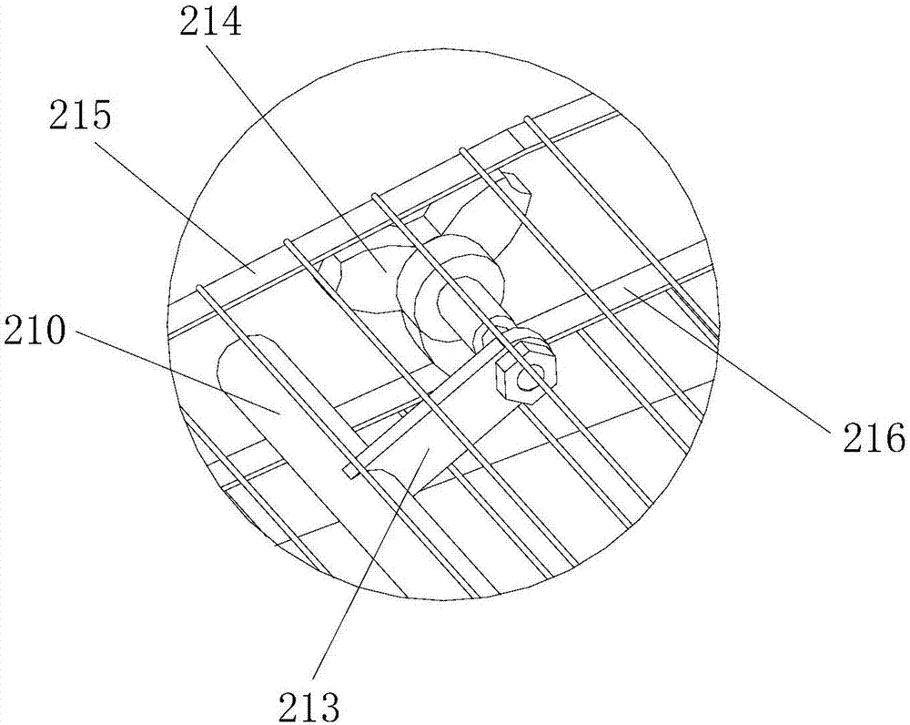
[0033] figure 1 It is a schematic structural diagram of the transmission device provided in Embodiment 1 of the present invention; figure 2 for figure 1 rear view of image 3 for figure 1 Partial enlarged view of A in the center. see Figure 1 to Figure 3 As shown, the present embodiment provides a conveying device, including a frame, and the frame is provided with a driving shaft 201, a gearbox 202, a hydraulic pump 203, a first chain conveying mechanism 204 and a second chain conveying mechanism 205; the driving shaft 201 One end of the drive shaft 201 is used to drive the output shaft of the traction device, preferably, one end of the drive shaft 201 is connected to the output shaft of the traction device through a coupling 226, and the other end of the drive shaft 201 is connected to the input shaft of the gearbox 202. , the first output shaft of the gearbox 202 is connected with the transmission of the first chain conveying mechanism 204, the first chain conveying m...

Embodiment 2

[0052] Figure 4 A schematic structural view of a harvester for rhizome crops provided in Embodiment 2 of the present invention; Figure 5 for Figure 4 Partial enlarged view of B in middle; Image 6 for Figure 4 Partial enlarged view at C in middle; Figure 7 A schematic diagram of the shovel positioned on the ground in the rhizome crop harvester provided by Embodiment 2 of the present invention; Figure 8 It is a schematic diagram of the shovel and the cutting knife in the rhizome harvester provided by Embodiment 2 of the present invention extending below the ground. Figure 4 Not shown in the shaft coupling 226, the first chain conveyor mechanism 204 and the second chain conveyor mechanism 205; Figure 8 In , the arrow direction D indicates the forward direction of the tractor driving the frame. In this embodiment, both the front end and the rear end are defined with reference to the forward direction. see Figure 4 to Figure 8 As shown, this embodiment provides a ...


PUM


Abstract

The invention relates to the technical field of agricultural harvesting machines, in particular to a conveying device and a tuber crop harvester with the conveying device. The conveying device comprises a machine frame, and the machine frame is provided with a driving shaft, a gearbox, a hydraulic pump, a first chain conveying mechanism and a second chain conveying mechanism, wherein the driving shaft is used for being in transmission connection with an output shaft of a traction device, and the other end of the driving shaft is in transmission connection with an input shaft of the gearbox; the first chain conveying mechanism is used for removing soil and impurities on the outer surfaces of tuber crops, and an impurity separation roller is arranged between the first chain conveying mechanism and the second chain conveying mechanism; the impurity separation roller is matched with the first chain conveying mechanism and used for removing leaves of the tuber crops; a guide roller is arranged above the second chain conveying mechanism and used for guiding the tuber crops into a lifting cage; the hydraulic pump is used for providing power for the second chain conveying mechanism and the guide roller. The tuber crops can be separated from the impurities such as the leaves, the soil and weeds, so that the efficiency is improved.

Description

technical field [0001] The invention relates to the technical field of agricultural harvesting machinery, in particular to a conveying device and a rhizome crop harvester using the device. Background technique [0002] As the planting area of ​​root crops (such as sugar beets, potatoes, etc.) in my country has increased year by year, their harvesting has entered a state of mechanization, which greatly reduces the intensity of manual labor, saves time and effort, and is highly efficient. Driven by the traction device, the excavating device digs out the soil, debris and root crops together, and then is loaded into the truck by the conveying device for transportation. [0003] Since a large amount of soil, leaves, plastic film and other sundries are mixed with root crops, in the process of crop processing, it is necessary to manually remove a large amount of soil, leaves, weeds and plastic film and other sundries, which is time-consuming and laborious, resulting in Production ...

Claims


Application Information

Patent Timeline
IPC IPC(8): A01D27/02A01D17/08A01D33/00A01D33/02A01D33/08
CPCA01D17/08A01D27/02A01D33/00A01D33/02A01D33/08
Inventor 郭天伟
Owner 承德万联机械制造有限公司
Why Eureka
Try Eureka