
Gas flooding and discharging sterilizer

A sterilizer and pan-gas technology, applied in disinfection, chemical instruments and methods, separation methods, etc., can solve problems such as hidden dangers of life, health and infection

Pending Publication Date: 2017-11-07
ZHEJIANG PEIJIEER MEDICAL TECH
View PDF5 Cites 0 Cited by
  • Summary
  • Abstract
  • Description
  • Claims
  • Application Information

AI Technical Summary

Problems solved by technology

[0002] The current urban construction has been in a period of rapid development, and dense high-rise buildings can be seen everywhere. Improving the sanitation and discharge facilities of closed septic tanks has been an indispensable key facility in construction from ancient times to the present, especially the vast majority of modern medical institutions. Surrounded by densely populated high-rise buildings, especially the infectious disease medical buildings of medical institutions are intensive areas where infectious patients are treated and lived, and the sanitary discharge of infectious disease medical areas is more airtight, because some of the feces of infectious patients The bacteria with stubborn infectious diseases are discharged into the damp and airtight septic tank for reproduction, and the construction and use principle of septic tank and urinal is to use the atmospheric air pressure to discharge the feces in the urinal under the action of attraction. Into the septic tank, so the stubborn bacteria in the feces and the bacteria in the septic tank are discharged into the atmosphere at the same time, leaving a serious infection risk to people's life and health through air transmission

Method used


Image

  • Gas flooding and discharging sterilizer
  • Gas flooding and discharging sterilizer
  • Gas flooding and discharging sterilizer

Examples


Embodiment Construction

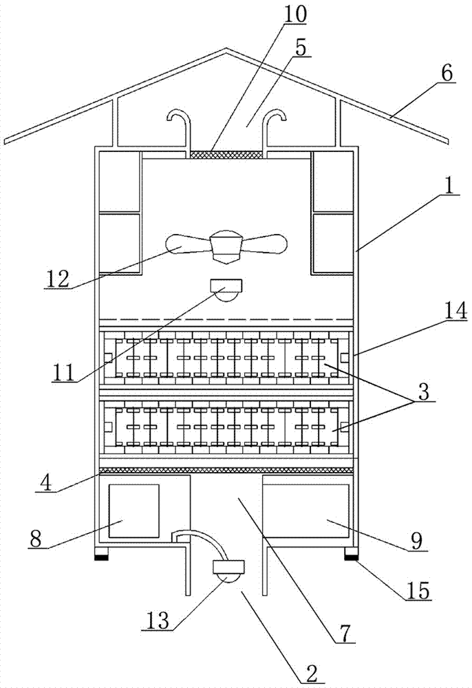
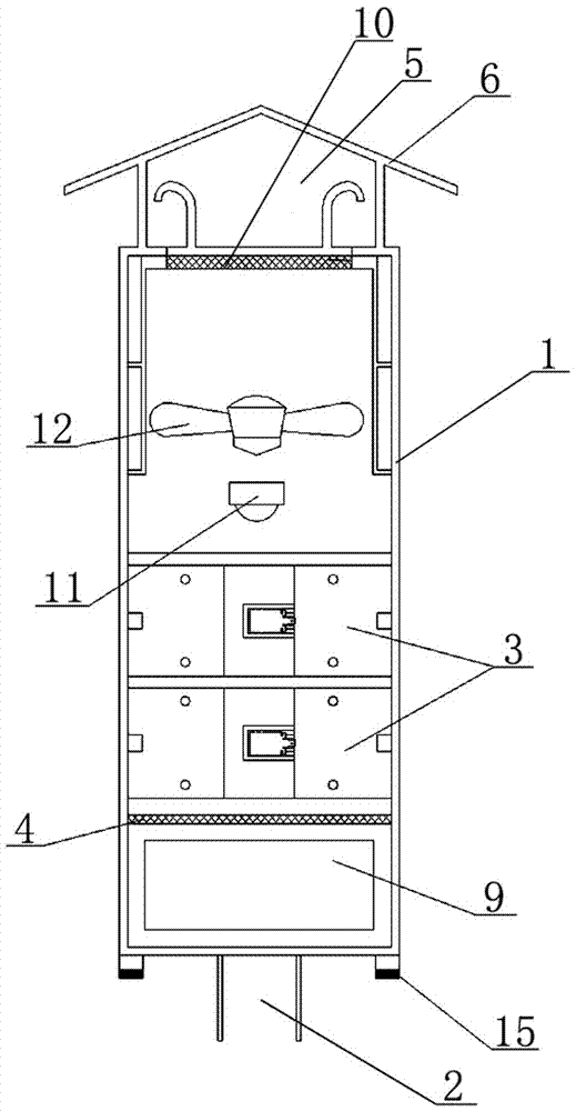
[0016] The present invention will be described in detail below in conjunction with accompanying drawing: figure 1 , 2 As shown, a kind of pan gas exhaust sterilizer described in the present invention, it comprises a cylinder type or box type vertically placed cabinet 1, and the bottom of described cabinet 1 is provided with a pan gas discharge port 2, and cabinet 1 interior is installed with At least one or more sterilization and disinfection devices 3, at least one layer of filter screen 4 for filtering particulate pollutants is arranged above the pan air discharge port 2 below the sterilization and disinfection devices 3, installed above the top exhaust outlet 5 A windproof and rainproof cover 6 is arranged or an exhaust pipe for discharging gas is connected on the top exhaust outlet 5 .

[0017] As shown in the figure, the pan gas discharge port 2 is arranged in the middle of the bottom of the cabinet 1, and a pan gas inlet passage 7 connected to the sterilization and disi...


PUM

PropertyMeasurementUnit
Thicknessaaaaaaaaaa
Diameteraaaaaaaaaa

Abstract

The invention discloses a gas flooding and discharging sterilizer which comprises a cylindrical or tank type vertical case, wherein a flooding gas inlet is formed in the bottom of the case; at least one or more than one sterilization disinfection devices are mounted inside the case; at least one layer of a filtering net for filtering off granular pollutants is arranged above the flooding gas inlet below the sterilization disinfection devices; a rain and windproof cover is mounted above a top exhaust hole, or an exhaust tube for discharging gases is connected with the top exhaust hole; the flooding gas inlet is formed in the middle of the bottom of the case; a flooding gas inlet channel which is communicated with the sterilization disinfection devices via the filtering net is formed inside the case; a power supply system and an intelligent main control device which is connected with the sterilization disinfection devices are respectively mounted on two sides of the flooding gas inlet channel; an upper sterilization disinfection device and a lower sterilization disinfection device which are connected in parallel are mounted inside the case; another filtering net is also mounted at the top exhaust hole of the case. The gas flooding and discharging sterilizer has the characteristics of being simple in structure, convenient to mount and use and the like.

Description

technical field [0001] The invention relates to a device which is mainly used for pan-gas exhaust disinfection in sanitary discharge facilities such as closed septic tanks, and belongs to the technical field of exhaust disinfection facilities. Background technique [0002] The current urban construction has been in a period of rapid development, and dense high-rise buildings can be seen everywhere. Improving the sanitation and discharge facilities of closed septic tanks has been an indispensable key facility in construction from ancient times to the present, especially the vast majority of modern medical institutions. Surrounded by densely populated high-rise buildings, especially the infectious disease medical buildings of medical institutions are intensive areas where infectious patients are treated and lived, and the sanitary discharge of infectious disease medical areas is more airtight, because some of the feces of infectious patients The bacteria with stubborn infectio...

Claims


Application Information

Patent Timeline
IPC IPC(8): A61L9/22B01D46/10
CPCA61L9/22B01D46/10A61L2209/11A61L2209/14
Inventor 罗炳灿罗毅解厉毅项文通钱娟芬赵莎
Owner ZHEJIANG PEIJIEER MEDICAL TECH
Learn More