A scr denitration device

A technology of denitrification and rectification device, which is applied in the field of flue gas purification, can solve the problems of reduced denitrification efficiency, long distance between reducing agent and flue gas, uneven mixing of reducing agent and flue gas, etc., to achieve the effect of improving uniformity and preventing shaking

Active Publication Date: 2020-09-01
CHINA NEW ERA INT ENG CORP
View PDF9 Cites 0 Cited by
  • Summary
  • Abstract
  • Description
  • Claims
  • Application Information

AI Technical Summary

Problems solved by technology

[0002] Nitrogen oxides are the main harmful gases in the flue gas produced by fuel combustion, which mainly include NO and NO 2 At present, SCR denitrification devices are mainly used to purify flue gas. The principle is to convert nitrogen oxides in flue gas into harmless nitrogen and water under the action of reducing agents and catalysts, so that nitrogen in flue gas Oxygen compound removal, in which the mixing of reducing agent and flue gas is a key step, the current SCR denitrification device generally has the problem of long distance required for the mixing of reducing agent and flue gas, and uneven mixing of reducing agent and flue gas, which will lead to smoke Insufficient gas reduction reaction reduces denitrification efficiency

Method used


Image

  • A scr denitration device
  • A scr denitration device
  • A scr denitration device

Examples


Embodiment Construction

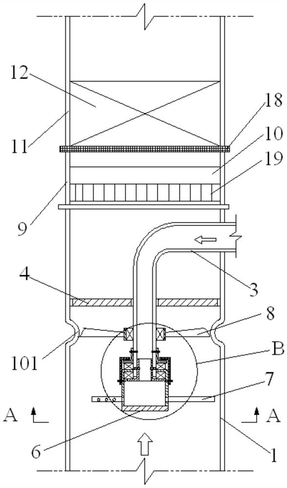
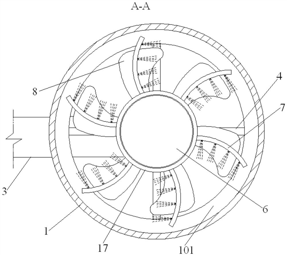
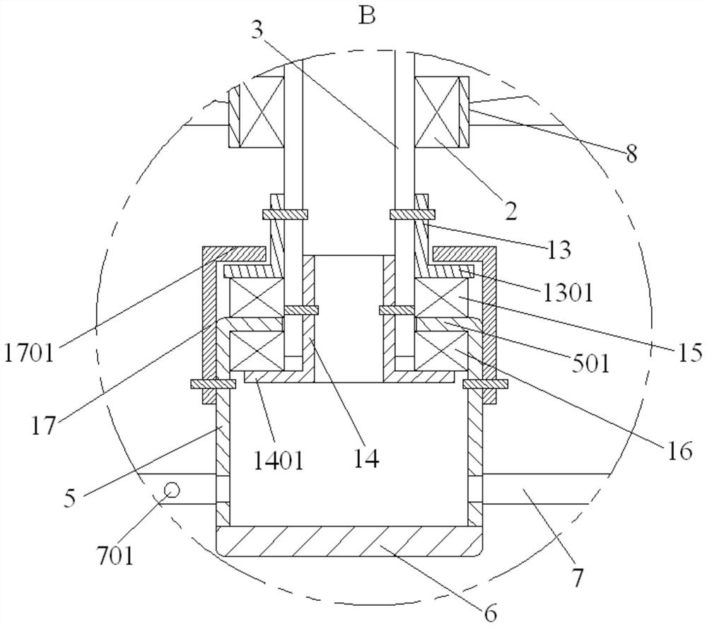
[0026] refer to Figure 1 to Figure 3, the embodiment of the present invention proposes a kind of SCR denitrification device, is used for carrying out denitrification treatment to flue gas, comprises: intake mixing section 1, rotary drum 5, wind impeller 8, rectifying section 9 and catalytic section 11; 1 is connected with the flue gas discharge pipeline 2, and the air intake mixing section 1 is provided with a reducing agent supply pipe 3 and a fixing frame 4, and the outlet end of the reducing agent supply pipe 3 is fixed on the fixing frame 4, and the reducing agent supply pipe 3 The inlet end of the intake port passes out of the side wall of the intake mixing section 1; the rotary drum 5 is rotated and assembled on the port of the outlet end of the reducing agent supply pipe 3, and the rotary drum 5 communicates with the reducing agent supply pipe 3, and the rotary drum 5 The other end is connected with an end cover 6, and the side wall of the drum 5 is connected with a pl...


PUM


Abstract

The invention discloses an SCR denitrification device which comprises a gas inlet mixing section, a rotating cylinder, a fan impeller, a rectification section and a catalysis section. A reducing agent supply pipe and a fixing frame are arranged inside the gas inlet mixing section, the outlet end of the reducing agent supply pipe is fixed to the fixing frame, the reducing agent supply pipe is led out of the gas inlet mixing section; the rotating cylinder is rotationally assembled at the outlet end of the reducing agent supply pipe, a plurality of spraying pipes are connected to the side wall of the rotating cylinder, a plurality of backlash spraying holes are uniformly formed in the side wall of each spraying pipe, and the axial lead of each backlash spraying hole and the axial lead of the rotating cylinder are orthogonal; a hub of the fan impeller is rotationally assembled on the side wall of the reducing agent supply pipe; the rectification section and the gas inlet mixing section are connected, and a rectification device is arranged inside the rectification section; one end of the catalysis section is connected with the rectification section, and the catalysis section is filled with a catalyzer module. According to the SCR denitrification device, the sprayed reducing agent can be mixed with boiler flue gas to be uniform within a short period of time, and the denitrification efficiency can be improved.

Description

technical field [0001] The invention belongs to the technical field of flue gas purification, and in particular relates to an SCR (Selective Catalytic Reduction, selective catalytic reduction technology) denitrification device. Background technique [0002] Nitrogen oxides are the main harmful gases in the flue gas produced by fuel combustion, which mainly include NO and NO 2 At present, SCR denitrification devices are mainly used to purify flue gas. The principle is to convert nitrogen oxides in flue gas into harmless nitrogen and water under the action of reducing agents and catalysts, so that nitrogen in flue gas Oxygen compound removal, in which the mixing of reducing agent and flue gas is a key step, the current SCR denitrification device generally has the problem of long distance required for the mixing of reducing agent and flue gas, and uneven mixing of reducing agent and flue gas, which will lead to smoke Insufficient gas reduction reaction reduces denitrification ...

Claims


Application Information

Patent Timeline
Patent Type & Authority Patents(China)
IPC IPC(8): B01D53/90B01D53/88B01D53/56
CPCB01D53/8631B01D53/88B01D53/90B01D2251/20B01D2258/0283
Inventor 彭文辉牛琪贾磊张军刚苏建华李姗姗刘莎
Owner CHINA NEW ERA INT ENG CORP
Why Eureka
Try Eureka