
Special feeding and blanking device for numerical control machine tool

A numerical control machine tool and quantity technology, applied in the field of numerical control machine tools, can solve the problems of inability to purchase a machine tool loading and unloading device, difficult to disassemble and remove, troublesome installation, etc., and achieve the effects of simple structure, good practicability and convenient installation.

Inactive Publication Date: 2017-11-07
佛山市夏云智能装备有限公司
View PDF0 Cites 6 Cited by
  • Summary
  • Abstract
  • Description
  • Claims
  • Application Information

AI Technical Summary

Problems solved by technology

For example, most of the traditional machine tool loading and unloading devices are fixedly installed on the machine tool and used in conjunction with the machine tool, so once installed and fixed, it is generally difficult to disassemble and remove, and the traditional machine tool loading and unloading devices are generally designed to be relatively large in size. It is even much larger than the machine tool. For those small and medium-sized enterprises, not only are they unable to purchase machine tool loading and unloading devices, but also due to the limited plant area, installation is also very troublesome. Therefore, machine tool loading and unloading devices are generally only used in large enterprises. Many small and medium-sized enterprises still use traditional manual loading and unloading. In view of the above situation, a simple loading and unloading device dedicated to CNC machine tools can be designed to solve the above problems.

Method used


Image

  • Special feeding and blanking device for numerical control machine tool
  • Special feeding and blanking device for numerical control machine tool
  • Special feeding and blanking device for numerical control machine tool

Examples


Embodiment Construction

[0017] The present invention will be further described below in conjunction with accompanying drawing and specific embodiment:

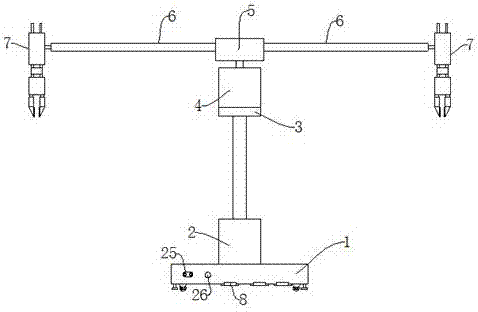
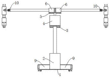
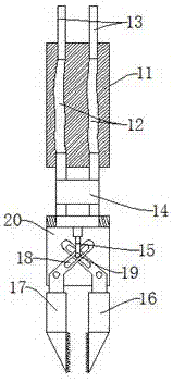
[0018] Such as Figure 1-Figure 4 As shown, a special loading and unloading device for CNC machine tools, including a base 1, the upper end of the base 1 is provided with a first electro-hydraulic push rod 2, and the first electro-hydraulic push rod 2 is used to push the pneumatic manipulator 7 to move up and down, Adjust the height of the pneumatic manipulator 7 from the ground, the upper end of the first electrohydraulic push rod 2 is provided with a first stepping motor 4, and the first stepping motor 4 is used to drive the pneumatic manipulator 7 around the first An electro-hydraulic push rod 2 rotates, the upper end of the first stepping motor 4 is provided with a second electro-hydraulic push rod 6, and the second electro-hydraulic push rod 6 is used to drive the pneumatic manipulator 7 along the mounting base 5 left and right Move, adjust the...


PUM


Abstract

The invention discloses a special loading and unloading device for a numerical control machine tool, comprising a base, a first electro-hydraulic push rod is arranged on the upper end of the base, a first stepping motor is arranged on the upper end of the first electro-hydraulic push rod, and The upper end of the stepping motor is provided with a second electrohydraulic push rod, the end of the second electrohydraulic push rod is provided with a second stepping motor, the second stepping motor is provided with a pneumatic manipulator, and the front of the base is provided with A foot switch, a battery box and a third electro-hydraulic push rod are arranged in the base, and a roller is arranged at the lower end of the base, and a hub motor is embedded in the roller. The beneficial effect is that the loading and unloading device of the CNC machine tool is simple in structure, small in size, convenient to disassemble and install, and low in cost, and is suitable for popularization and use by small and medium-sized enterprises; moreover, the bottom of the loading and unloading device is equipped with the above-mentioned rollers, which is convenient, flexible and practical to move Good sex.

Description

technical field [0001] The invention relates to the field of numerical control machine tools, in particular to a special loading and unloading device for numerical control machine tools. Background technique [0002] The machine tool loading and unloading device is an automatic or semi-automatic mechanical device that sends the workpiece to be processed to the processing position on the machine tool and removes the processed workpiece from the processing position, also known as the automatic workpiece loading and unloading device. The machine tool loading and unloading device is used for semi-automatic machine tools with high efficiency, short maneuvering time and frequent workpiece loading and unloading, which can significantly improve production efficiency and reduce physical labor. The loading and unloading device of the machine tool is also an indispensable auxiliary device to form an automatic production line. It can be seen that the machine tool loading and unloading ...

Claims


Application Information

Patent Timeline
Patent Type & Authority Applications(China)
IPC IPC(8): B23Q7/04
CPCB23Q7/046
Inventor 李锦潮
Owner 佛山市夏云智能装备有限公司
Learn More