Intelligent dynamic metering production system

An intelligent dynamic and automatic feeding technology, applied in loading/unloading, container, packaging and other directions, can solve the problems such as the huge difference in the height of the mold cavity between the tonnage model and the size, the vibration source cannot be completely solved, and the weighing error of the vibration source, etc. The effect of convenient and fast discharging, simple structure and controllable speed

Inactive Publication Date: 2017-11-07
郑州星和凯贸易有限公司
7 Cites 5 Cited by

AI-Extracted Technical Summary

Problems solved by technology

[0002] Existing powder molding in the refractory and forging industries requires manual measurement and weighing of the bulk material according to the customer's calibration quantity requirements, and then pours it into the cavity of the screw press forming mold, which has high labor intensity, low work efficiency, and human errors. Large, unable to achieve accurate measurement, resulting in unstable product performance, material pollution to the environment, and greater harm to the human body, greatly hindering production, resulting in high production costs and low output
[0003] At present, there are some feeding equipments on the market. Due to the normal production process in the powder molding industry o...

Abstract

The invention belongs to the field of molding devices in the powder industry, and in particular, relates to an intelligent dynamic metering production system. The system mainly consists of a bin prediction device, a precise weighing device, an automatic feeding device, an automatic double lifting mechanism, a rail translation device, a machine body fixing mechanism and the like; the lower part of the bin prediction device is in butt joint with the precise weighing device; the lower part of the precise weighing device is in butt joint with the automatic feeding device; the automatic feeding device is fixed on the machine body fixing mechanism through the automatic double lifting mechanism; the machine body fixing mechanism transversely moves through the rail transition device arranged at the bottom; the operation stability of whole equipment is achieved; meanwhile, continuity of the whole production system can be effectively guaranteed; the purpose of continuous operation is realized; and the system is high in control precision, stable in operation, controllable in speed, simple in structure, low in failure rate, long in service life, high in safety and low in labor intensity, can achieve automatic control, reduces manual operation, and improves working conditions of workers.

Application Domain

Large containersLoading/unloading

Technology Topic

Automatic controlContinuous operation +3

Image

  • Intelligent dynamic metering production system
  • Intelligent dynamic metering production system
  • Intelligent dynamic metering production system

Examples

  • Experimental program(1)

Example Embodiment

[0024] The specific embodiments of the present invention will be described in detail below with reference to the accompanying drawings.
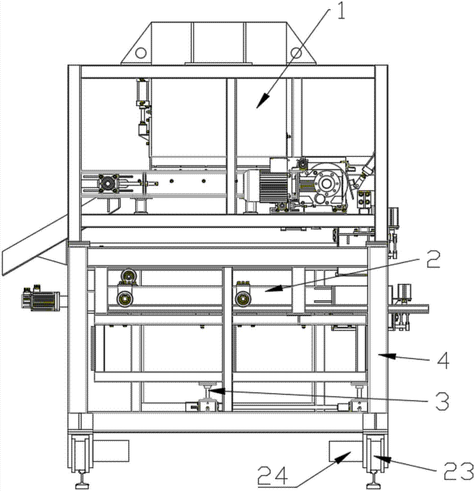
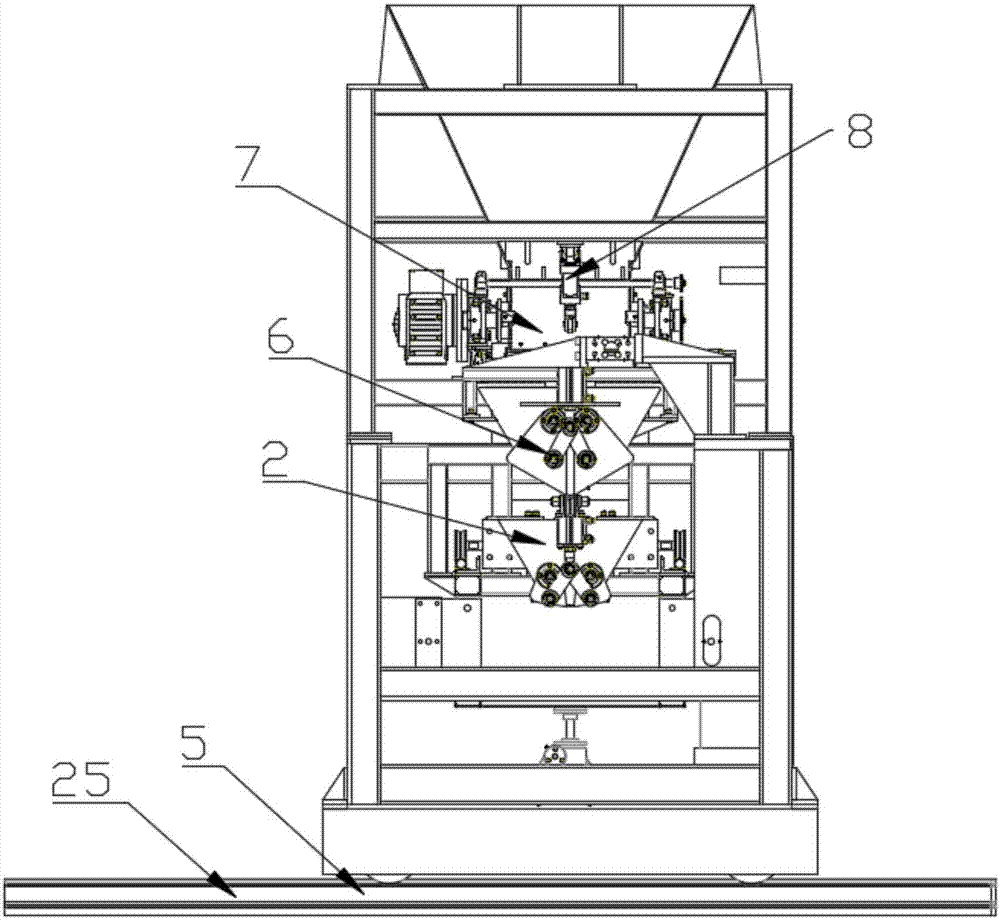
[0025] see Figure 1-2 , an intelligent dynamic measuring and forecasting system, which is mainly composed of a silo forecasting device 1, a precise weighing device 6, an automatic feeding device 2, an automatic double lifting mechanism 3, a rail translation device 5, and a body fixing mechanism 4. The lower part of the device 1 is connected to the precise weighing device 6, and the lower part of the precise weighing device 6 is connected to the automatic feeding device 2. The automatic feeding device 2 is fixed on the body fixing mechanism 4 through the automatic double lifting mechanism 3, and the body fixing mechanism 4 is set through the bottom track. The translation device 5 performs lateral movement.
[0026] The silo prediction device 1 includes a pretreatment silo, a stirring device 8 is arranged inside the pretreatment silo, a discharge port baffle is arranged at the discharge port of the pretreatment silo, and a discharge port baffle is arranged on the discharge port baffle. Plate adjustment device, the bottom of the pretreatment silo is connected to the precise weighing device through the large feeding device and the small feeding device in turn, and the large feeding device and the small feeding device are respectively composed of a large belt conveyor and a small belt conveyor.
[0027] see image 3 The precise weighing device 6 includes an electronic lining hopper 10 and a load cell 9 . Support plates 11 are respectively provided on both sides of the electronic lining hopper 10 , and the supporting plates 11 are fixedly connected to the load cell bracket 13 located on the top of the supporting plate 11 through a fixing rod 12 . The load cell 9 is placed horizontally on the upper part of the electronic liner 10 and is connected to the load cell bracket 13 through the first fixing frame 14 on one side, and is connected to the body fixing mechanism 16 through the second fixing frame 15 on the other side. The electronic lining hopper 10 is a bottomless hopper in the shape of an inverted quadrangular pyramid; the electronic lining hopper 10 is provided with a revolving gate device, and the revolving gate device is driven by the air cylinder 20 to form a discharge port for material conveying.
[0028] see Figure 4-5 The automatic feeding device 2 includes a servo motor 23, a feeding roller 24, a feeding guide rail 25, a pushing device and a silo 28. The pushing device includes a pushing plate 26 and a pushing rod 27 fixed on the pushing plate 26. The pushing The device is fixedly connected to the silo 28 through the push rod 27, and the two ends of the push plate 26 are connected to the feeding roller 24 through the roller shaft 29. The feeding roller 24 is powered by the servo motor 23 to move forward and backward on the feeding rail 25. To move, the servo motor 23 is connected with the automatic control system. The silo 28 is a bottomless hopper in the shape of an inverted quadrangular pyramid; the silo 28 is provided with a revolving gate device, and the revolving gate device is driven by a cylinder to form a discharge port for material conveying.
[0029] see Figure 3-5 The electronic lining hopper 10 and the silo revolving door device include a left revolving door device 17 and a right revolving door device 18 with the same left and right symmetrical arrangement, and the left revolving door device 17 includes a front door and a rear door. , and the bottom baffle connecting the front and rear material doors, the front and rear material doors are fixed on the trapezoidal side walls of the electronic lining hopper or silo through the rotating shaft 21; the left rotating material door device 17 When docked with the bottom baffle of the right rotating material gate device 18, the electronic lining hopper or the side wall of the hopper is connected to the bottom baffle; the cylinder 20 is fixed on the trapezoidal side of the electronic lining hopper or silo by fixing bolts Lever cylinder on the upper part of the wall.
[0030] see Figure 3-5 The lever cylinder is fixed on the upper part of the trapezoidal side wall of the electronic liner or the silo by fixing bolts. The front gate of the left revolving gate device 17 and the right revolving gate device 18 is provided with a support lever 19. The support lever 19 The free end is connected with the rotary bearing of the free end of the pressing lever 22 through a rotary bearing; the pressing lever and the two supporting levers form a triangular lever group.
[0031] see Figure 1-2 The automatic double lifting mechanism 3 is composed of an electric double screw lifting platform.
[0032] see Figure 1-2 The rail translation device 5 includes a roller 23 fixed on the bottom of the body fixing mechanism 4 and a roller motor 24 for controlling the roller 23 to move on the roller guide rail 25 .
[0033]The working principle of the present invention: the intelligent dynamic metering and feeding system is installed on the guide rail on the ground as a whole. When the screw press replaces the mold, the whole can move horizontally or vertically. After the mold is replaced, the intelligent metering and feeding system returns to its original position and operates After the personnel adjust the height of the automatic feeding device through the automatic double lifting mechanism, the operator can set the weight value of the material required by the press in the automatic control system of the intelligent metering feeding system. After setting the material calibration value, The automatic control system sends the collected signals to the central processing unit of the automatic control system through the precise weighing device, and the central processing unit of the automatic control system processes and issues instructions to each terminal.
[0034] First, the material is pretreated by the pretreatment silo device to the large belt conveyor and the small belt conveyor for coarse and fine feeding, and then enters the precise weighing device for measurement. When the material in the electronic liner reaches the weight value, it is weighed. The sensor feeds back the signal to the automatic control system, and the pretreatment silo stops feeding. At this time, the lever cylinder on the electronic liner drives the pressing lever to drive the left and right revolving door devices. Turn the clock to the right, the bottom baffle of the docked rotating device is opened to form a discharge port, and the material is transported from the electronic liner to the silo of the automatic feeding device
[0035] After that, the automatic feeding device pushes the material to the mold cavity of the screw press through the feeding roller and feeding guide rail, and then feeds the material. The discharge port of the silo is opened in the same way as the electronic hopper. , the automatic control system drives the servo motor to drive the silo to return to the original position and enter the next cycle of the intelligent conveying prediction system.
[0036] Finally, the screw press starts the process of material forming to realize the automatic production of the whole process. If you change the brick type and weight, repeat the above steps.
[0037] The above descriptions are only preferred implementation cases of the present invention, and do not limit the technical scope of the present invention. Therefore, any improvements, deformations and modifications made to the above embodiments according to the technical essence of the present invention still belong to the technical solutions of the present invention. scope of protection.

PUM

no PUM

Description & Claims & Application Information

We can also present the details of the Description, Claims and Application information to help users get a comprehensive understanding of the technical details of the patent, such as background art, summary of invention, brief description of drawings, description of embodiments, and other original content. On the other hand, users can also determine the specific scope of protection of the technology through the list of claims; as well as understand the changes in the life cycle of the technology with the presentation of the patent timeline. Login to view more.

Similar technology patents

Turning gradient control valve

InactiveCN102410270ASmooth oil flow switchingGuaranteed stability
Owner:LANZHOU UNIVERSITY OF TECHNOLOGY

Pixel circuit and driving method thereof, electroluminescent display panel and display device

ActiveCN108335668AAvoid voltage instabilityGuaranteed stability
Owner:HEFEI XINSHENG OPTOELECTRONICS TECH CO LTD +1

Classification and recommendation of technical efficacy words

  • Guaranteed continuity
  • Guaranteed stability

A ccd-type colloidal gold immunochromatographic diagnostic test paper quantitative analysis system

InactiveCN102279263AGuaranteed stabilityAddressing Subjective Bias
Owner:杭州顿力医疗器械有限公司

General clamp for abrasive flow polishing of complicated hole surface

InactiveCN104551985AContinuous and stable flowGuaranteed stability
Owner:CHANGCHUN UNIV OF SCI & TECH

Laminated intelligent shock-isolation bearing capable of self-adaptively regulating cutting performance

InactiveCN101586641AGuaranteed stabilityThe interlayer displacement of the isolation layer is small
Owner:WUHAN UNIV OF TECH
Why Eureka
Try Eureka