Fluorescent traffic warning pile

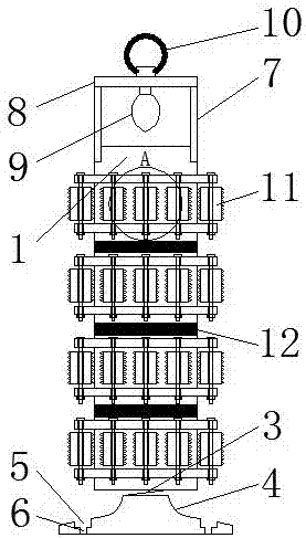
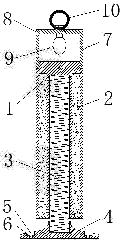
A warning post and traffic technology, applied in traffic signals, roads, road signs, etc., can solve the problems of easy bending, breaking and deformation of warning posts, and achieve the effects of avoiding wear, good fluorescent brightness, and enhanced buffering

Inactive Publication Date: 2017-11-07
王迅
View PDF0 Cites 3 Cited by
  • Summary
  • Abstract
  • Description
  • Claims
  • Application Information

AI Technical Summary

Problems solved by technology

[0003] The technical problem solved by the present invention is to overcome the defect that the traffic warning post in the prior art is easy to damage the surface of the car when it is hit by a car and the warning post itself is easy to bend, deform or even break, and to provide a fluorescent traffic warning post
The fluorescent traffic warning pile has the characteristics of strong cushioning effect, is not easy to cause the surface of the car to be worn, and is not easy to bend and break itself.

Method used


Image

  • Fluorescent traffic warning pile
  • Fluorescent traffic warning pile
  • Fluorescent traffic warning pile

Examples


Embodiment 1

[0022] According to the chemical formula TS-1 / Zn-Yb 5.5 Nb 6.5 V 3 o 17 The stoichiometric ratio of each element, according to the molar ratio Yb ion: Nb ion: V ion is 5.5:6.5:5

[0023] Respectively weigh ytterbium oxide Yb 2 o 3 , Nb(OH) 5 , Vanadium pentoxide V 2 o 5 , after grinding and mixing uniformly in an agate mortar, select the air atmosphere to pre-calcine at 420°C for 10 hours in a muffle furnace, then cool to room temperature, take out the sample, mix the mixture thoroughly again, and grind it evenly in the air atmosphere , calcined at 1050°C for 2 hours, cooled to room temperature, taken out and fully ground to obtain Yb 5.5 Nb 6.5 V 3 o 17 powder,

[0024] Take 5 copies of Yb 5.5 Nb 6.5 V 3 o 17 Add the powder to 5% nitric acid, and add 2 parts of TS-1 powder and 0.5 part of Zn powder,

[0025] After stirring for one hour, filter and wash repeatedly, and finally calcine in the air atmosphere at 1300°C for 3 hours, cool to room temperature, take ...

Embodiment 2

[0028] Yb 3 Nb 7 V 3 o17 The stoichiometric ratio of each element, according to the molar ratio Yb ion: Nb ion: V ion is 3:7:3

[0029] Respectively weigh ytterbium oxide Yb 2 o 3 , Nb(OH) 5 , Vanadium pentoxide V 2 o 5 , after grinding and mixing uniformly in an agate mortar, select the air atmosphere to pre-calcine at 420°C for 10 hours in a muffle furnace, then cool to room temperature, take out the sample, mix the mixture fully and grind evenly again, in the air atmosphere , calcined at 1050°C for 2 hours, cooled to room temperature, taken out and fully ground to obtain Yb 3 Nb 7 V 3 o 17 powder,

[0030] After stirring for one hour, filter and wash repeatedly, and finally calcine in the air atmosphere at 1300°C for 3 hours, cool to room temperature, take it out and grind it sufficiently to obtain the phosphor powder Yb 3 Nb 7 V 3 o 17 .

[0031] Coating preparation: Firstly, the unsaturated polyester resin solution and the methyl ethyl ketone peroxide solu...

Embodiment 3

[0033] The formula process is exactly the same as that of Example 1, except that the fluorescent powder is Yb 2.2 Nb 7.8 V 3 o 17

[0034] During the phosphor preparation process, the molar ratio of Yb ions: Nb ions: V ions is 2.2:7.8:3.


PUM


Abstract

The invention discloses a fluorescent traffic warning pile, which comprises a pile body, a buffer layer, a spring, a base, a mounting groove, a mounting hole, a top cover, a solar panel, a monitor, a pull ring, a buffer device, a roller fixing ring, a buffer roller, Through holes, tapped holes, bolts, nuts and fluorescent coatings. The center of the pile body is a hollow structure, and the side wall of the pile body is provided with a buffer layer, the top inner wall of the pile body is fixedly connected with a spring, the bottom of the spring is fixedly connected with a base, and several installation grooves are opened on the surface of the base, each installation There are installation holes in the grooves; a top cover is installed on the top of the pile body, and a solar panel is installed on the top of the top cover. The solar panel is electrically connected to a monitor, and the top of the solar panel is fixedly connected to a pull ring. The outer wall of the pile body Several groups of buffer devices are fixedly connected, and a fluorescent coating is arranged between each group of buffer devices.

Description

technical field [0001] The invention relates to the technical field of traffic facilities, in particular to a fluorescent traffic warning post. Background technique [0002] Traffic warning bollards are a common traffic safety facility with a wide range of applications. They can be used not only on concrete roads to separate lanes, but also in parking lots to remind parking locations. The traffic warning piles in the prior art are generally installed on the ground with iron materials or plastics. When the vehicle touches the warning piles, the warning piles will scrape off the paint of the car body. dented, and the warning piles will be bent, deformed or even broken due to the impact of the car, and the damaged warning piles must be removed afterwards, and new warning piles must be reinstalled, resulting in waste. When used at night, in poor light In the case of accidents, the driver will not be able to see the warning pole clearly. Contents of the invention [0003] The...

Claims


Application Information

Patent Timeline
Patent Type & Authority Applications(China)
IPC IPC(8): E01F15/00E01F9/669E01F9/615E01F9/627E01F15/10E01F9/688
CPCE01F15/003E01F9/617E01F9/629E01F9/669E01F9/688E01F15/006
Inventor 王迅王晓春
Owner 王迅
Why Eureka
Try Eureka