
Metal buffering component and bufferingmechanism based on metal buffering component

A technology of cushioning mechanism and cushioning parts, which is applied in the direction of mechanical equipment, shock absorbers, instruments, etc., can solve the problems of large structural size and difficulty in controlling the magnitude and duration of the impact force, and achieve high specific strength and specific stiffness and low production cost. Inexpensive, satisfying control effect

Inactive Publication Date: 2017-11-07
NANJING UNIV OF SCI & TECH
View PDF4 Cites 0 Cited by
  • Summary
  • Abstract
  • Description
  • Claims
  • Application Information

AI Technical Summary

Problems solved by technology

In order to solve the problem that the structural size of the conventional buffer device is too large and the size of the impact force and the duration of the action are difficult to control after buffering

Method used


Image

  • Metal buffering component and bufferingmechanism based on metal buffering component
  • Metal buffering component and bufferingmechanism based on metal buffering component
  • Metal buffering component and bufferingmechanism based on metal buffering component

Examples


Embodiment Construction

[0035] In order to illustrate the technical scheme and technical purpose of the present invention, the present invention will be further introduced below in conjunction with the accompanying drawings and specific embodiments.

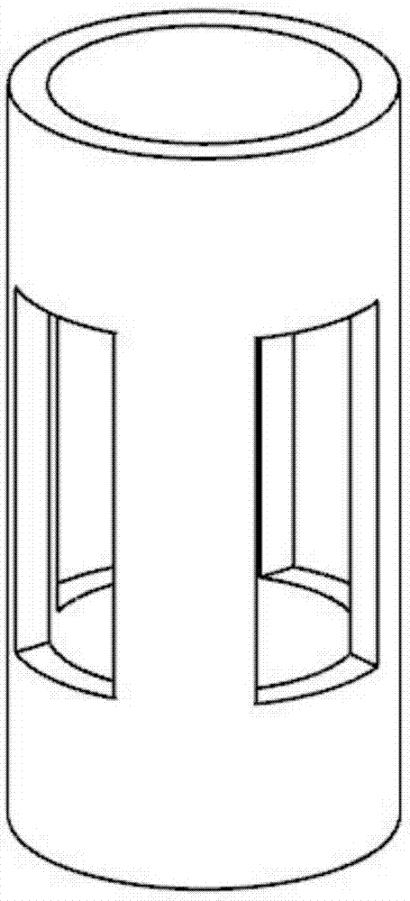
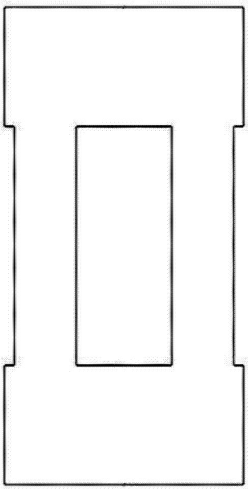
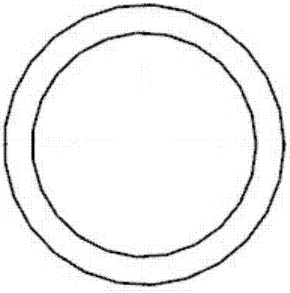
[0036] combine Figure 1~3 , a metal buffer of the present invention, the metal buffer is a hollow cylindrical structure, and the side wall in the middle of the circumference of the cylindrical structure is evenly provided with n through holes communicating with the internal cavity, n≥2; the through holes It is a rectangular hole; the material of the metal buffer is copper;

[0037] Preferably, the number n of said through holes is 4. According to the simulation calculation results of the optimization software, when the number of openings on the side wall of the metal buffer is 4, the metal buffer can obtain a relatively suitable stiffness characteristic and achieve a good Buffer effect;

[0038] Further, the elastic modulus of the copper material is ...


PUM

PropertyMeasurementUnit
elastic modulusaaaaaaaaaa
lengthaaaaaaaaaa
Poisson's ratioaaaaaaaaaa

Abstract

The invention discloses a metal buffering component and a buffering mechanism based on the metal buffering component. The metal buffering component is of a hollow cylindrical structure. Four rectangular holes communicating with an inner cavity are evenly formed in the circumferential side wall of the middle portion of the cylindrical structure. The metal buffering component is made of copper. The buffering mechanism based on the metal bufferingcomponent comprises a cylinder body, a drop hammer, a supporting frame, a mounting base, a guide ball, a first stop block, the metal buffering component and a second stop block, wherein the cylinder body, the mounting base and the supporting frame are fixedly connected, and the drop hammer is arranged in the cylinder body and can slide freely to impact the guide ball; the guide ball, the first stop block, the metal buffering component and the second stop block are sequentially placed in a cavity of the mounting base in a contact mode; and the mounting base is connected to an impacted object. According to the buffering mechanism based on the metal buffering component, in the collision process, the metal buffering component deforms plastically to absorb energy, so that pulse force generated by collision is converted into constant collision force to be output and acts for a certain period of time, and requirements in engineering occasions can be well met.

Description

technical field [0001] The invention relates to the technical field of buffering, in particular to a metal buffering piece and a buffering mechanism based on the metal buffering piece. Background technique [0002] There are various impact problems in the project, such as vehicle collision, ship docking, aircraft collision with birds, collision between two carriages when the train brakes, impact of the gas jet on the launching device when the rocket and missile are launched, etc.; in these impacts At the moment of acceleration, a huge acceleration is often generated, causing varying degrees of damage or destruction to related mechanical parts, structures and personnel. Therefore, it is necessary to take measures to reduce the impact force and prolong the action time of the impact force, that is, the buffering method often used in engineering. Buffering is to use the relevant buffer to absorb the collision energy and delay the impact force to achieve the purpose of reducing ...

Claims


Application Information

Patent Timeline
Patent Type & Authority Applications(China)
IPC IPC(8): F16F1/02F16F7/00G06F17/50
CPCF16F1/025F16F7/00G06F30/17G06F30/23
Inventor 李军高功卓赵鑫
Owner NANJING UNIV OF SCI & TECH
Learn More