
Nested planetary reducer converting reciprocating motion into unidirectional motion

A technology of planetary reducer and reciprocating motion, which is applied in one-way clutches, mechanical drive clutches, clutches, etc., can solve the problems of increased cumulative error of the transmission system, small speed regulation range, and poor accuracy retention, and achieves good accuracy retention , wide range of speed regulation, excellent structure

Inactive Publication Date: 2017-11-07
ANHUI UNIV OF SCI & TECH
View PDF4 Cites 13 Cited by
  • Summary
  • Abstract
  • Description
  • Claims
  • Application Information

AI Technical Summary

Problems solved by technology

[0003] The traditional planetary reducer can only adjust the speed of one-way input motion. For some transmission systems that need to change the direction of rotation in real time, if the reciprocating motion is to be converted into one-way motion, a special reversing device needs to be installed. It not only increases the complexity of the transmission system, but also increases the cumulative error of the entire transmission system, reducing the transmission accuracy of the system; traditional planetary reducers are generally used in fields with high precision requirements, and in actual use due to the distribution of working load Due to the influence of uneven factors, the accuracy of the reducer is gradually reduced, and the accuracy retention is poor under high-strength working conditions
In addition, the traditional planetary reducer has a small speed regulation range and poor structural flexibility, which cannot better adapt to different production environments.

Method used


Image

  • Nested planetary reducer converting reciprocating motion into unidirectional motion
  • Nested planetary reducer converting reciprocating motion into unidirectional motion
  • Nested planetary reducer converting reciprocating motion into unidirectional motion

Examples


Embodiment Construction

[0020] The present invention is further described below:

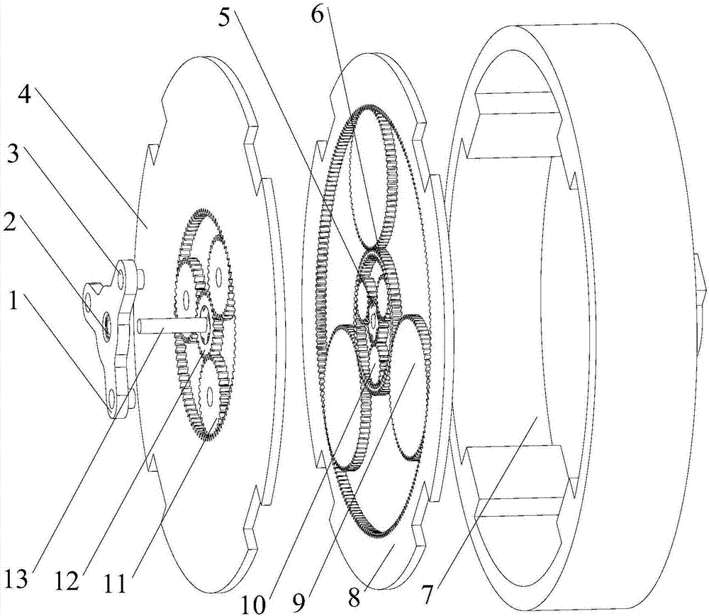
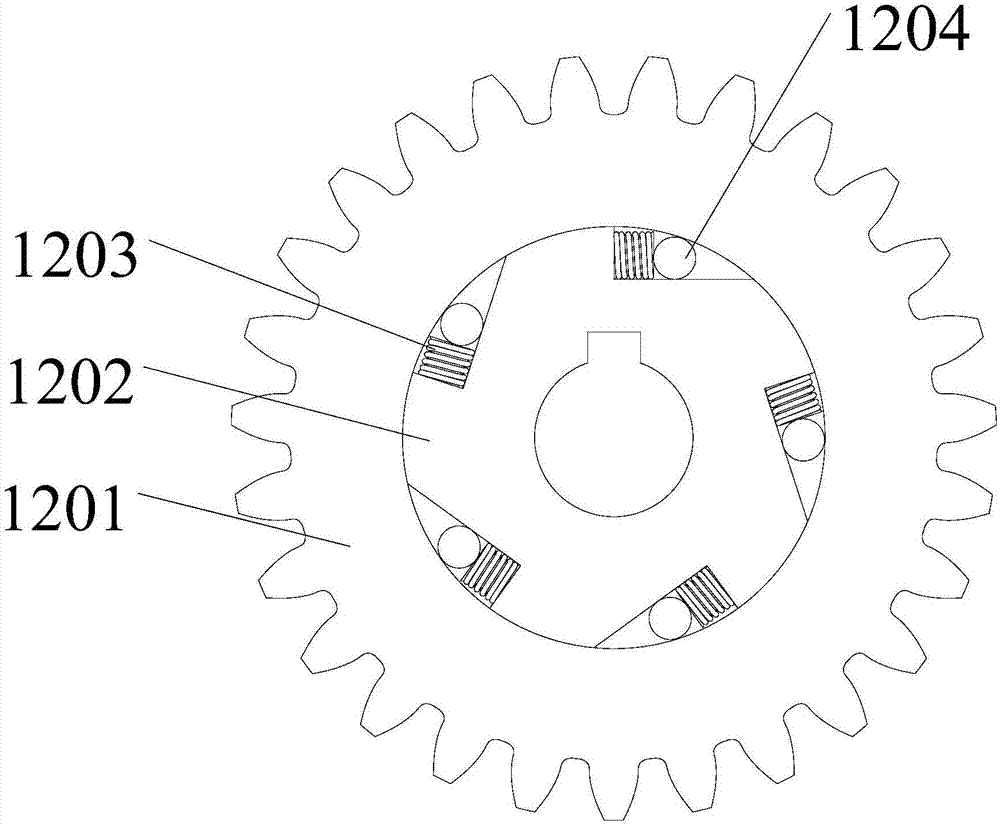
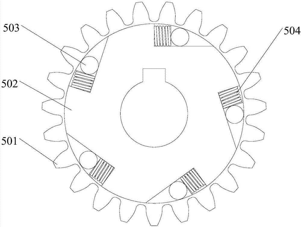
[0021] combine figure 1 , figure 2 , image 3 , Figure 4 , a nested planetary reducer structure that converts reciprocating motion into one-way motion, including front row overrunning clutch 12, rear row overrunning clutch 5, compound gear 6, output end cover 7, planet carrier 1, deep groove ball Bearing 2 , front row outer ring gear 4 , rear row outer ring gear 8 , rear row outer planetary gear 9 , rear row inner planetary gear 10 , front row planetary gear 11 , input shaft 13 and fixed pin shaft 3 . When the motion is input through the input shaft 13 in a clockwise direction, since the installation direction of the front overrunning clutch 12 and the rear overrunning clutch 5 is opposite, at this time the rear overrunning clutch 5 is in a disengaged state, and the front overrunning clutch 12 is engaged. Drive the output end cover 7 backward to output the movement in a counterclockwise direction; when the moveme...


PUM


Abstract

The invention discloses a nested planetary reducer converting reciprocating motion into unidirectional motion. The nested planetary reducer comprises a front overrun clutch, a rear overrun clutch, a composite gear, an output end cover, a planet carrier, a deep groove ball bearing, a front outer gear ring, a rear outer gear ring, rear outer-side planet wheels, rear inner-side planet wheels, front planet wheels and an input shaft. When motion is input clockwise, the front overrun clutch is subjected to engagement and drives the output end cover to output motion counterclockwise after primary direction changing. When motion is input counterclockwise, the rear overrun clutch is subjected to engagement, after the direction of a rear nested planetary transmission mechanism is changed twice, motion is output counterclockwise, and finally, the purpose of converting reciprocating motion into unidirectional motion is achieved. The nested planetary reducer integrates direction changing with speed changing, the complexity, caused by a reversing device, of a transmission system is reduced, and in addition, the nested planetary reducer is large in transmission, flexible in structure, high in smoothness and good in precision retaining ability.

Description

technical field [0001] The invention relates to a structure of a nested planetary reducer which converts reciprocating motion into unidirectional motion and its working principle. Background technique [0002] Planetary reducers are widely used in various machines, mechanical equipment and transmission systems due to their compact structure, small size, high transmission efficiency and high precision. For example, lifting machinery, machine tools and servo drive systems, etc. [0003] The traditional planetary reducer can only adjust the speed of the unidirectional input motion. For some transmission systems that need to change the direction of rotation in real time, if the reciprocating motion is to be converted into a unidirectional motion, a special reversing device needs to be installed. It not only increases the complexity of the transmission system, but also increases the cumulative error of the entire transmission system, reducing the transmission accuracy of the sys...

Claims


Application Information

Patent Timeline
Patent Type & Authority Applications(China)
IPC IPC(8): F16H1/32F16D23/12F16D41/061F16H57/023
CPCF16D23/12F16D41/061F16H1/321F16H57/023F16D2125/44F16D2121/14F16H2001/327
Inventor 郭靖陈阳杨晴晴张标
Owner ANHUI UNIV OF SCI & TECH
Learn More