Single winding annular fluxgate current sensor

A current sensor and fluxgate technology, applied in the direction of only measuring current, voltage/current isolation, measuring current/voltage, etc., can solve the problem that the signal-to-noise ratio of the fluxgate signal is not high enough, reduce product reliability, and limit product versatility and other problems to achieve the effect of increasing product reliability, structural stability, and enhancing signal strength

Inactive Publication Date: 2017-11-07
SHANDONG INST OF AEROSPACE ELECTRONICS TECH
View PDF3 Cites 4 Cited by
  • Summary
  • Abstract
  • Description
  • Claims
  • Application Information

AI Technical Summary

Problems solved by technology

[0002] The existing fluxgate current sensor technology is a dual-winding scheme, such as figure 1 As shown, the fluxgate signal is generated in the primary winding 11 through the excitation circuit 13, but the signal-to-noise ratio of the fluxgate signal is not high enough. If it is directly amplified, the current in the measured current line can be measured through the fluxgate signal The signal accuracy is not high, so the fluxgate signal needs to be conditioned by the signal conditioning circuit after being filtered by the filter circuit 14, and then the compensation magnetic field is generated on the secondary winding 12 by the feedback compensation circuit 16 to form a closed-loop feedback to improve the signal-to-noise ratio
In addition, the existing technology uses a silicon steel magnetic core, which makes the product larger and limits the versatility of the product; at the same time, the primary and secondary windings will increase the process complexity and reduce the product reliability.

Method used


Image

  • Single winding annular fluxgate current sensor
  • Single winding annular fluxgate current sensor
  • Single winding annular fluxgate current sensor

Examples


Embodiment Construction

[0035] The present invention will be described in detail below with reference to the accompanying drawings and examples.

[0036] A single-winding toroidal fluxgate current sensor, comprising a fluxgate probe and a signal processing circuit;

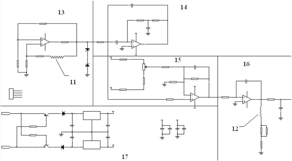
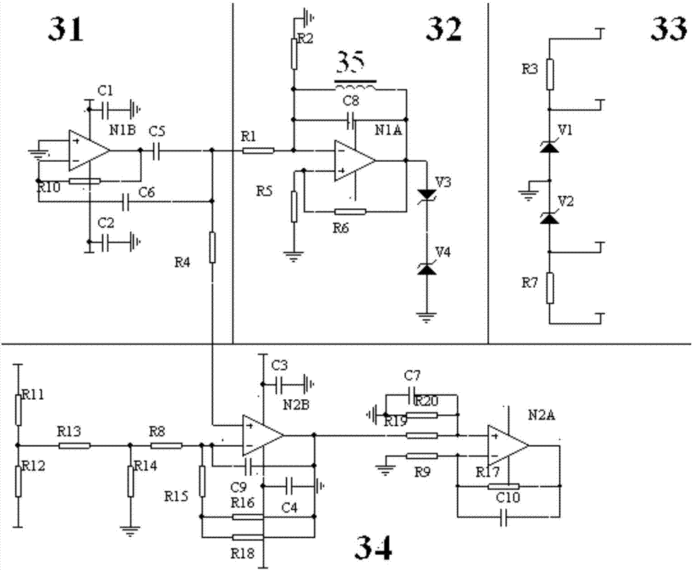
[0037] Such as image 3As shown, it is a schematic diagram of the sensor circuit of the present invention, and the signal processing circuit includes a filter circuit 31, an excitation circuit 32, a power supply circuit 33, a signal conditioning circuit 34 and a fluxgate probe 35, wherein the power supply circuit 33 provides the signal conditioning circuit 34 with Stabilize the voltage, the excitation circuit 32 provides an excitation signal to the fluxgate probe 35, so that the fluxgate probe 35 generates a fluxgate signal, the filter circuit 31 filters the fluxgate signal generated by the fluxgate probe 35, and the signal conditioning circuit 34 Correcting the zero point offset and sensitivity error of the signal processing circuit an...


PUM


Abstract

The present invention provides a single winding annular fluxgate current sensor. The single winding annular fluxgate current sensor adopts a permalloy as magnetic core material of a fluxgate probe, a generated fluxgate signal has an enough high signal to noise ratio, a secondary winding is not need to generate a compensation magnetic field to form the enclosed loop feedback, and the error correction and the signal amplification can be carried out by entering a signal conditioning circuit directly, so that according to the present invention, a conventional dual-winding coil is changed into a single-winding coil, the conversion from a current signal to the fluxgate signal and to a voltage signal can be realized by just using one primary winding, and accordingly, the current signal in a measured current line can be measured, not only the product process is simplified, but also the product reliability is increased, and the precision is higher when the current signal of the measured current line is measured. According to the present invention, the signal conditioning circuit is also improved, and by conditioning an output signal via a two-stage amplifying circuit, the situation that the product performance does not degrade is guaranteed.

Description

technical field [0001] The invention belongs to the technical field of current sensors, in particular to a single-winding annular fluxgate current sensor. Background technique [0002] The existing fluxgate current sensor technology is a dual-winding scheme, such as figure 1 As shown, the fluxgate signal is generated in the primary winding 11 through the excitation circuit 13, but the signal-to-noise ratio of the fluxgate signal is not high enough. If it is directly amplified, the current in the measured current line can be measured through the fluxgate signal The signal accuracy is not high, so the fluxgate signal needs to be filtered by the filter circuit 14 and conditioned by the signal conditioning circuit, and then the feedback compensation circuit 16 generates a compensation magnetic field on the secondary winding 12 to form a closed-loop feedback to improve the signal-to-noise ratio. In addition, the existing technology uses a silicon steel magnetic core, which makes...

Claims


Application Information

Patent Timeline
Patent Type & Authority Applications(China)
IPC IPC(8): G01R19/00G01R15/18
CPCG01R19/0092G01R15/18
Inventor 丁俊鹏赵旭万丽徐春明王阳钟贻兵张乐君
Owner SHANDONG INST OF AEROSPACE ELECTRONICS TECH
Why Eureka
Try Eureka