Power factor correction method based on double-inductor double-voltage DC output circuit

A power factor correction, DC output technology, applied in output power conversion devices, high-efficiency power electronic conversion, electrical components, etc., can solve problems such as voltage levels not meeting requirements

Active Publication Date: 2017-11-07
SHANGHAI MUNICIPAL ELECTRIC POWER CO
View PDF2 Cites 4 Cited by
  • Summary
  • Abstract
  • Description
  • Claims
  • Application Information

AI Technical Summary

Problems solved by technology

In addition, in the three-level inverter, the voltage level provided by the tr

Method used


Image

  • Power factor correction method based on double-inductor double-voltage DC output circuit
  • Power factor correction method based on double-inductor double-voltage DC output circuit
  • Power factor correction method based on double-inductor double-voltage DC output circuit

Examples


Embodiment Construction

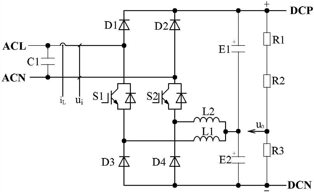
[0031] see figure 1 In order to better understand the technical solution of the present invention, the inventors of the present invention will describe in detail below through specific embodiments in conjunction with the accompanying drawings:

[0032] like figure 1 The first dual-inductance dual-voltage circuit adopted for a power factor correction method based on a dual-inductance dual-voltage DC output circuit of the present invention includes: a first IGBT module S1 and a second IGBT module S2, a first power diode D1, The second power diode D2, the third power diode D3 and the fourth power diode D4, the first power inductor L1 and the second power inductor L2, the first electrolytic capacitor E1 and the second electrolytic capacitor E2, the first voltage dividing resistor R1, the second Two voltage-dividing resistors R2 and a third voltage-dividing resistor R3, and a filter capacitor C1.

[0033] The first end of the filter capacitor C1 is connected to the live wire of t...


PUM


Abstract

The invention discloses a power factor correction method based on a double-inductor double-voltage DC output circuit. The double-inductor double-voltage circuit comprises an uncontrolled rectifier bridge circuit, a capacitance bridge circuit and a voltage division circuit, which are connected in parallel. The uncontrolled rectifier bridge circuit comprises a first bridge arm and a second bridge arm. The voltage division circuit comprises at least two resistors, which are connected in series in sequence. The voltage division circuit is provided with a DC side sampling end. The first bridge arm and the second bridge arm of the uncontrolled rectifier bridge circuit are connected with a power live wire and a power zero wire respectively, and a dual-gate switch is arranged between the power live wire and the power zero wire to form an input voltage and input current sampling end. A first power inductor L1 and a second power inductor L2 are arranged between the first and second bridge arms of the uncontrolled rectifier bridge circuit and the capacitance bridge circuit respectively. The method carries out inner-ring power factor correction on input voltage ui and input current iL collected at the input voltage and input current sampling end and carries out outer-ring voltage control on the output voltage uo collected at the DC side sampling end of the voltage division circuit.

Description

technical field [0001] The invention relates to a power factor correction method based on a dual-inductance dual-voltage DC output circuit in the field of power electronics. Background technique [0002] The power electronic conversion device powered by a single-phase AC power supply can be used in application fields such as switching power supplies, high-power frequency converters, and power factor correctors (PFC). In order to reduce the harmonic pollution to the AC power grid, some standards for limiting current harmonics have been introduced abroad, such as the IEC 1000-3-2Class D standard, which requires AC input power to take measures to reduce the current harmonic content and improve the power factor. [0003] The passive var compensation device is bulky, while the active var compensation is not only small in size, but also has high energy conversion efficiency. The step-up power factor corrector makes the current flowing through the power inductor sinusoidal and in ...

Claims


Application Information

Patent Timeline
IPC IPC(8): H02M1/42
CPCH02M1/4233Y02B70/10
Inventor 俞瑾华杨喜军刘鑫徐剑李佳文俞艳静胡海敏朱淑敏陈震金琪周圣栋解蕾周振敏沙征陈庆沈佳祯朱毅强李文雯严小恺徐方袁心怡金利尔黄子豪刘莹旭郁悦周顺福
Owner SHANGHAI MUNICIPAL ELECTRIC POWER CO
Why Eureka
Try Eureka