Non-isolation type three-phase three-level V2G charge-discharge topological structure and control method therefor

A topology, three-level technology, used in battery circuit devices, current collectors, electric vehicles, etc., can solve the problems of large common-mode voltage, difficult to find, etc., to suppress spikes, reduce switching times, and ensure The effect of the energy bidirectional flow characteristic

Inactive Publication Date: 2017-02-01
NORTH CHINA ELECTRIC POWER UNIV (BAODING) +1
View PDF3 Cites 23 Cited by
  • Summary
  • Abstract
  • Description
  • Claims
  • Application Information

AI Technical Summary

Problems solved by technology

On the other hand, the positive and negative small vectors participate in the synthesis of the reference vector at the same time, which will cause the system output common-mode voltage to have a large amplitude. method

Method used


Image

  • Non-isolation type three-phase three-level V2G charge-discharge topological structure and control method therefor
  • Non-isolation type three-phase three-level V2G charge-discharge topological structure and control method therefor
  • Non-isolation type three-phase three-level V2G charge-discharge topological structure and control method therefor

Examples


specific Embodiment approach

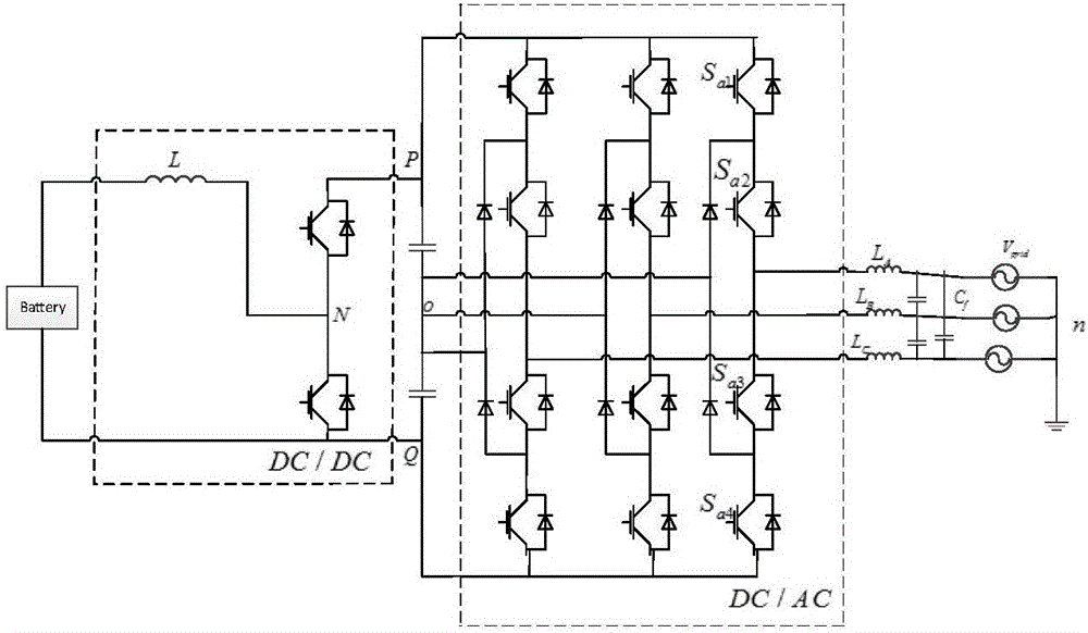
[0047] The logical relationship of the control strategy is as follows Figure 5 shown. The details are as follows: Let the electromotive force of the three-phase grid be e a ,e b ,e c , connected to the connection of the upper and lower arms of each phase bridge arm through the three-phase linear inductance L, the currents of the three-phase grid side are respectively i a ,i b ,i c , the AC / DC part adopts the double closed-loop control structure of the voltage outer loop and the current inner loop, the reference voltage vector signal is obtained through the double closed loop, and sent to the SVPWM control module to generate twelve control pulses, which are sent to the AC / DC part twelve switch tube, the control strategy of the present invention proposes at the SVPWM control module (see Figure 5 The SVPWM signal generation module in).

[0048] from Image 6 It can be seen that the ordered letter combination composed of P, O and N represents 27 groups of switch states, ...


PUM


Abstract

The invention discloses a non-isolation type three-phase three-level V2G charge-discharge topological structure. The non-isolation type three-phase three-level V2G charge-discharge topological structure comprises a main circuit module and a control circuit module, wherein the main circuit module comprises three parts in cascading manner, including a DC/DC part, an H bridge balance circuit and a DC/AC part; a vehicle-mounted power battery is connected to a direct current positive bus and a direct current negative bus through a bidirectional half-bridge converter; the H bridge balance circuit and two voltage-division capacitors C1 and C2 are arranged between the direct current positive bus and the direct current negative bus, and the direct current positive bus and the direct current negative bus are connected with the output end of the bidirectional half-bridge converter in parallel; the direct current buses are connected with a diode clamping type three-level PWM converter; a three-phase alternating current power supply live wire is connected to connecting places of upper and lower bridge arms of each phase of the bridge arms through a three-phase LC filter; the direct current buses are positioned in the H bridge balance circuit; according to the H bridge balance circuit, an IGBT switch tube Tb1 is in anti-parallel connection with a rapid recovery diode, or the switch tube Tb1 with an in-vivo parasitic diode is connected with a one-way conducive free-wheeling diode Db1 in series to form one side bridge arm, and a balance inductor Lb1 is connected in the middle thereof; the other end of the balance inductor is connected to a direct current side middle point; the bridge arms on the two sides are connected with a shared negative electrode and a shared positive electrode; and namely, the upper ends of the bridge arms are both connected to the direct current positive bus while the lower ends of the bridge arms are both connected to the direct current negative bus.

Description

technical field [0001] The invention belongs to the technical field of power electronics applications, and in particular relates to a non-isolated three-phase three-level V2G charging and discharging topology structure and a control method thereof. Specifically, it is a non-isolated V2G system topology and control method that is suitable for energy interaction between distributed power sources and AC power grids under modern power conversion technology, and meets the needs of common-mode voltage suppression and midpoint potential balance coordinated control. Background technique [0002] Facing the increasingly severe energy crisis, it has become the general trend to promote the development of the electric vehicle industry and realize the two-way energy interaction (Vehicle-to-Grid, V2G) between vehicles and power grids. At present, the development of V2G technology tends to be integrated. BYD's two-way inverter charging and discharging technology has revolutionized various...

Claims


Application Information

Patent Timeline
Patent Type & Authority Applications(China)
IPC IPC(8): H02J7/02H02M7/797H02M1/12H02M1/32B60L11/18
CPCB60L55/00H02J7/022H02M1/12H02M1/32H02M7/797H02M1/123Y02T10/92
Inventor 颜湘武肖志恒邓浩然李艺曲伟
Owner NORTH CHINA ELECTRIC POWER UNIV (BAODING)
Why Eureka
Try Eureka