
Manufacturing method for cross-shaped column rotation circular pipe column structure and cross-shaped column rotation circular pipe column structure thereof

A manufacturing method and technology of cross columns, which are applied in the direction of columns, pier columns, pillars, etc., can solve the problems of poor dimensional accuracy, high difficulty in component processing, and poor integration of cross parts and round pipe parts, etc., to reduce welding Deformation and residual stress, ensuring appearance and dimensional quality, and good overall structural stress effect

Active Publication Date: 2017-11-10
湖北精工钢结构有限公司
View PDF8 Cites 9 Cited by
  • Summary
  • Abstract
  • Description
  • Claims
  • Application Information

AI Technical Summary

Problems solved by technology

However, steel column components are generally the most important structural components of the entire steel structure. If the manufacturing method is unscientific and unreasonable, it will affect the structural safety of the entire building.
[0004] The application number is 201520287301.7, and the patent name is "A Large-Scale Cross Round Tube Conversion Node", which discloses a large cross round tube conversion node with a compact structure that can be used for concrete steel columns such as high-rise buildings and railway stations; this application only Part of it extends into the inside of the round tube, the overall structure is not well stressed, and the structure is too complicated, too many welds and joint breakpoints will inevitably lead to stress concentration of the components, and at the same time, the processing and manufacturing of the components is too difficult, and the internal and external quality of the components is difficult. ensure
[0005] The application number is 201220273707.6, and the patent name is "Steel Structure Circular Tube Column and Cross Column Section Conversion Node Structure", which discloses a conversion node structure through the cross section conversion of box-shaped columns and conical tubes and cross columns; the cross section of this application It is not well combined with the round pipe part; it is impossible to realize industrial production. The general steel structure involves the transformation of the round structure of the sky and the earth, and can only be made of cast steel nodes. This patent can not be realized theoretically by assembling plates. The connection with the box column is the connection between the arc surface and the plane, which is generally difficult to realize
[0006] The application number is 201120460180.3, and the patent name is "Cross Round Tube Combination Steel Column", which discloses a cross round tube composite steel column that can replace reinforced concrete; Intersecting at the docking point will inevitably lead to poor dimensional accuracy of component processing and difficulty in ensuring the internal and external quality of welds, thus affecting structural safety

Method used


Image

  • Manufacturing method for cross-shaped column rotation circular pipe column structure and cross-shaped column rotation circular pipe column structure thereof
  • Manufacturing method for cross-shaped column rotation circular pipe column structure and cross-shaped column rotation circular pipe column structure thereof
  • Manufacturing method for cross-shaped column rotation circular pipe column structure and cross-shaped column rotation circular pipe column structure thereof

Examples


Embodiment Construction

[0045] The implementation of the present invention will be described in detail below in conjunction with the accompanying drawings, but they do not constitute a limitation to the present invention, and are only examples. At the same time, the advantages of the present invention are clearer and easier to understand through the description.

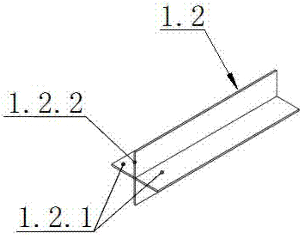
[0046] Referring to the accompanying drawings, it can be known that the manufacturing method of the cross-column-to-cylindrical column structure is characterized in that it comprises the following steps:

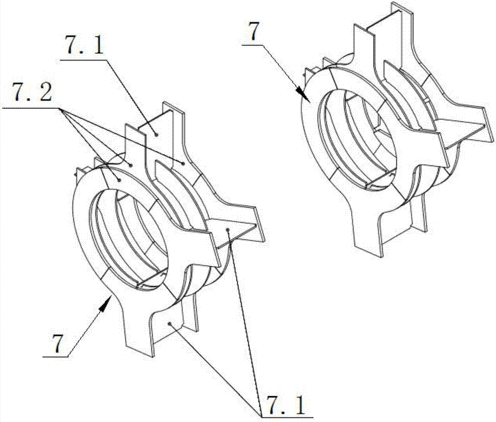
[0047] Step 1: Assembling the annular H-shaped corbel: Assemble four annular flange plates 7.1 and four annular H-shaped corbel webs 7.2 to form the first annular H-shaped corbel 7; refer to the first annular H-shaped corbel The assembly method of 7 assembles the second annular H-shaped corbel 7; reserve carbon dioxide gas protection for the strip formed between the annular flange plate 7.1 of the two annular H-shaped corbels 7 and the we...


PUM

PropertyMeasurementUnit
Diameteraaaaaaaaaa

Abstract

The invention discloses a manufacturing method of a cross-shaped column rotation circular pipe column structure. The method comprises the following steps that four annular flange plates and four annular H-shaped bracket webs are assembled into a first annular H-shaped bracket; in reference to the assembling method of the first annular H-shaped bracket, a second annular H-shaped bracket is assembled; a cross-shaped column web is assembled; a cross-shaped stiffening plate is assembled; a box type part and a cross-shaped column part are assembled, and two box type part flange plates, two box type part webs, the cross-shaped column web and the cross-shaped stiffening plate are assembled into the box type part and the cross-shaped column part; a circular pipe part is assembled, and the cross-shaped stiffening plate and four arc plates are assembled into a circular pipe part; sealing plates are assembled, and the eight sealing plates are assembled to an upper port and a lower port of the circular pipe part; and the two annular H-shaped brackets are assembled to the outer wall of the circular pipe part. The manufacturing method has the beneficial effect that the integral stress effect of the structure is good. The invention further discloses the cross-shaped column rotation circular pipe column structure adopting the manufacturing method of the cross-shaped column rotation circular pipe column structure.

Description

technical field [0001] The invention relates to the technical field of building steel structure processing and manufacturing, more specifically, it relates to a manufacturing method of a cross-column-turned-cylindrical-column structure. The present invention also relates to a cross-column-turned-cylindrical-column structure that adopts the manufacturing method of the cross-column-turned-cylindrical-column structure. Background technique [0002] Today's domestic building steel structures are showing a trend of diversification and complexity. The cross-shaped, box-shaped, and circular tube structures are more and more applied to steel structure projects by virtue of their unique advantages in the building structure system. . [0003] With the maturity of technology in my country's construction steel structure processing field and the rapid development of the industry, the single application of cross-shaped, box-shaped, round pipe and other structures has gradually transforme...

Claims


Application Information

Patent Timeline
IPC IPC(8): B23K9/16E04C3/32
CPCB23K9/0026B23K9/16E04C3/32
Inventor 程登张发荣姜殿忠王笛金欣夏远炎杨杰
Owner 湖北精工钢结构有限公司
Learn More