Electro-hydraulic compound brake system for recovering braking energy of electric fork-lift

A technology of braking energy recovery and electro-hydraulic compounding, applied in electric braking systems, braking safety systems, electric vehicles, etc., can solve problems such as uncomfortable braking, wear of friction pairs, and reduced brake life, and achieve improved The effect of improving energy utilization, ensuring braking safety, and prolonging service life

Pending Publication Date: 2017-11-14
ANHUI HELI CO LTD
View PDF7 Cites 7 Cited by
  • Summary
  • Abstract
  • Description
  • Claims
  • Application Information

AI Technical Summary

Problems solved by technology

If the electric braking intensity of the accelerator pedal release brake is strengthened, the braking deceleration is too large, and the braking feeling is uncomfortable
[0003] The service braking of some small-tonnage battery forklifts adopts full-motor braking. Although high-intensity braking can be achieved by setting regenerative braking parameters to meet the requirements of safe braking distance, compared with releasing the brake with the accelerator pedal, it recovers more energy. , but if the large-tonnage four-wheel counterbalanced battery forklift uses full motor braking, because there is no participation of hydraulic brakes, once the electric brake fails, the braking safety of the vehicle cannot be guaranteed; the large-tonnage four-wheel counterbalanced battery forklift The service brake adopts full hydraulic brake. Frequent use of the brake will cause wear and heat of the friction pair. If used for a long time, the braking performance will decrease and the life of the brake will be shortened.

Method used


Image

  • Electro-hydraulic compound brake system for recovering braking energy of electric fork-lift
  • Electro-hydraulic compound brake system for recovering braking energy of electric fork-lift

Examples


Embodiment Construction

[0014] The present invention will be further described below in conjunction with accompanying drawing:

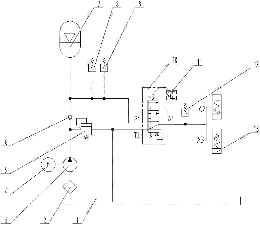
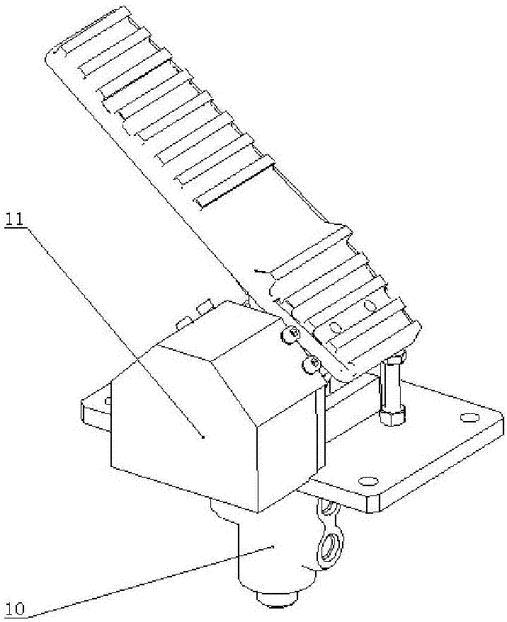
[0015] Such as figure 1 As shown, the electro-hydraulic composite braking system for electric forklift braking energy recovery in this embodiment includes oil suction filter 2, overflow valve 5, check valve 6, accumulator 7, three-position three-way full hydraulic pressure The power brake valve 10, the service brake device, the gear pump 3 controlled by the motor 4, the control device for controlling the rotation or stop of the motor 4, the pedal angle sensor 11 connected with the pedal of the forklift, and the intake filter 2 The oil port extends into the oil in the hydraulic oil tank 1, the oil outlet of the oil suction filter 2 communicates with the oil inlet of the gear pump 3, and the oil outlet of the gear pump 3 is respectively connected to the overflow valve 5 and the single valve through a three-way pipe. It is connected to the oil inlet of valve 6, and the oil ou...


PUM


Abstract

The invention relates to an electro-hydraulic compound brake system for recovering the braking energy of an electric fork-lift. The system comprises a suction filter, wherein the oil inlet of the suction filter extends into oil in a hydraulic oil tank, and the oil outlet of the suction filter is communicated with the oil inlet of a gear pump; the oil outlet of the gear pump is respectively communicated with the oil inlet of an overflow valve and the oil inlet of a one-way valve; the oil outlet of the overflow valve is respectively communicated with an oil return opening T1 of a three-position three-way full-hydraulic power brake valve and the hydraulic oil tank; the oil outlet of the one-way valve is respectively communicated with an energy accumulator and the oil inlet P1 of the three-position three-way full-hydraulic power brake valve; the oil outlet of the three-position three-way full-hydraulic power brake valve is connected with a service braking device; and a pedal angle sensor is connected with the brake pedal rotating shaft of the three-position three-way full-hydraulic power brake valve through a coupler. The electro-hydraulic compound brake system realizes maximized regenerating braking energyrecovery by coordinated control of electro-braking and hydraulic braking, so that braking safety is guaranteed, and energy utilization is improved.

Description

technical field [0001] The invention belongs to the technical field of forklift braking, and in particular relates to an electro-hydraulic composite braking system for recovering braking energy of an electric forklift. Background technique [0002] At present, most battery forklifts realize regenerative braking by releasing the accelerator pedal, and at the same time perform braking energy recovery. Since the accelerator pedal releases the braking strength setting is weak, it is used for regular deceleration and light braking during driving, and the braking torque Small, less recoverable energy. If the electric braking strength of the accelerator pedal release brake is strengthened, the braking deceleration will be too large, and the braking feeling will be uncomfortable. [0003] The service braking of some small-tonnage battery forklifts adopts full-motor braking. Although high-intensity braking can be achieved by setting regenerative braking parameters to meet the requir...

Claims


Application Information

Patent Timeline
Patent Type & Authority Applications(China)
IPC IPC(8): B60T13/58B60T13/74B60T17/22B60L7/10
CPCB60T13/58B60T13/74B60T17/22B60L7/10
Inventor 田原马庆丰陈伟林江博张杰陈仕胜
Owner ANHUI HELI CO LTD
Why Eureka
Try Eureka