Oil pressure type time difference brake device and assembly thereof

A braking device and hydraulic technology, applied in bicycle accessories, bicycle brakes, etc., can solve the problems of vehicle tail-flicking and crash accidents, and achieve the effect of improving braking efficiency and safety.

Active Publication Date: 2017-11-14
张瑞龙
View PDF6 Cites 0 Cited by
  • Summary
  • Abstract
  • Description
  • Claims
  • Application Information

AI Technical Summary

Problems solved by technology

[0002] At present, the brake systems of various vehicles, such as automobiles, the brakes of the front and rear wheels use a master cylinder to simultaneously drive the oil pressure output pipes corresponding to the brakes of the front and rear wheels to generate braking force. As a result, when the driver makes a braking action, although the master cylinder drives the brake oil pressure output pipes of the front and rear wheels at the same time to generate braking force, but because the rear wheels are farther from the master cylinder than the front wheels, the front wheel brakes are already activated. When starting the braking action, the rear wheel brakes only start to brake and wait half a beat. Because most vehicles adopt the rear wheel transmission structure, the front transmission starts to brake, and the rear wheels continue to output large kinetic energy. Risk Factors Caused by Vehicle Drift
[0003] As for two-wheel locomotives and bicycles, since the brake operating components of the front and rear wheels are respectively distributed on the left and right sides of the handle, the braking action of the front wheel or the rear wheel depends on the result of the rider's own operation. For this reason, It will also cause irreparable results due to the rider's operation error. For example, due to the common brake operation error, the front wheel brake is activated by mistake first, resulting in the continuous output of rear wheel power, resulting in a major crash accident.

Method used


Image

  • Oil pressure type time difference brake device and assembly thereof
  • Oil pressure type time difference brake device and assembly thereof
  • Oil pressure type time difference brake device and assembly thereof

Examples


Embodiment Construction

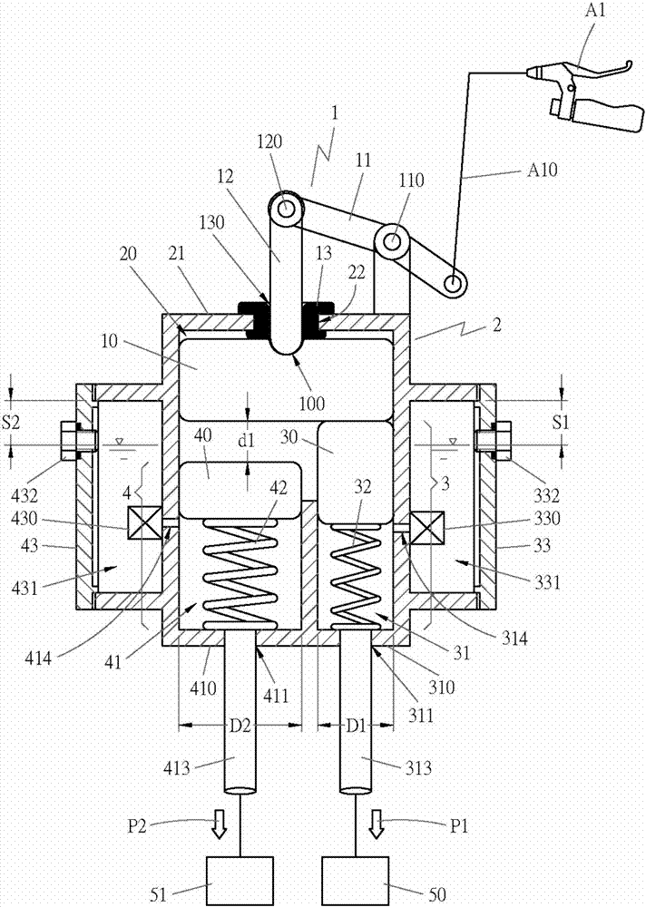
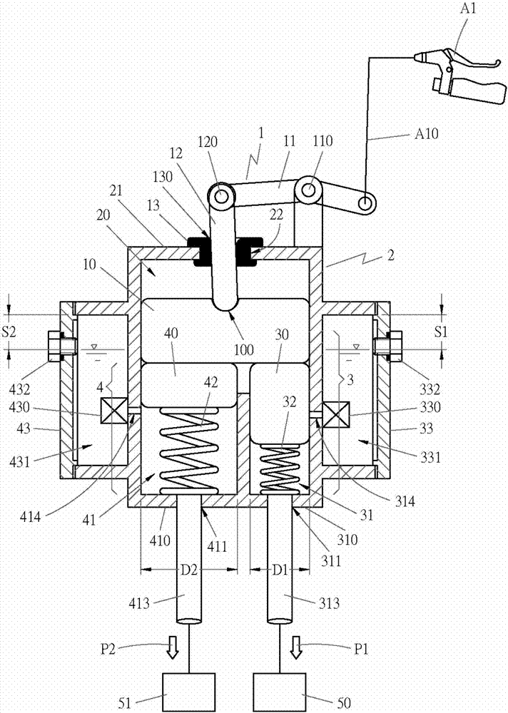
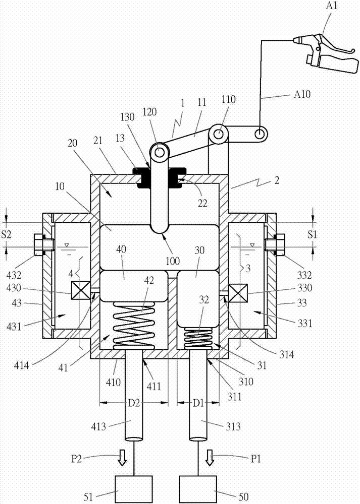
[0031] In order for examiners to further understand the hydraulic time difference brake device of the present invention, the best implementation is explained as follows with reference to the accompanying drawings:

[0032] Such as Figure 1~3 , the hydraulic time difference braking device of the present invention at least includes: a driving mechanism 1, which is linked with the brake operation assembly A1, the aforementioned driving mechanism 1 is provided with a push block 10, which is arranged on the top of the chamber 20 of the casing 2, and A coupling groove 100 is provided at the center of the push block 10 to facilitate coupling with the driving rod 11 . The aforementioned driving mechanism 1 is provided with a lever 11 again, and the lever 11 is provided with a fulcrum 110. The aforementioned lever 11 is located at one end of the fulcrum 110 and is combined with the cable line A10 of the brake operating assembly A1. 12 are mutually combined into movable fulcrum 120. ...


PUM


Abstract

The invention discloses an oil pressure type time difference brake device and an assembly thereof. The oil pressure type time difference brake device at least comprises a driving mechanism; the driving mechanism is provided with a pushing block, is arranged on the uppermost side of a cavity of a shell, and is started by dint of a brake operation module to enable the pushing block to generate a set displacement; a first piston of a first pump mechanism is driven to generate a displacement in real time so as to output first brake braking force to a rear wheel brake; and when the first piston of the first pump mechanism reaches a time difference of the distance of the set displacement, a second piston of a second pump mechanism is pushed to generate a displacement, and second brake braking force is output to a front wheel brake.

Description

technical field [0001] The present invention relates to a braking device, especially a hydraulic type time difference braking device. With a braking action of a rider or a driver, the first piston of the first pump mechanism reaches the set displacement distance within the time difference, which will add At the same time, push the second piston of the second pump mechanism to generate displacement, and output the second braking force to the front wheel brake. In this way, a braking action of the rider or driver can be achieved by the first pump mechanism and the second pump At the beginning, the mechanism generates the first braking force and the second braking force with a time difference, so that the rear wheel brake and the front wheel brake produce a braking action with a time difference, and then let the second braking force generated by the second pump mechanism It is greater than the first braking force generated by the first pump mechanism, so as to increase the brakin...

Claims


Application Information

Patent Timeline
Patent Type & Authority Applications(China)
IPC IPC(8): B62L3/02B62L3/08
CPCB62L3/023B62L3/08
Inventor 张瑞龙
Owner 张瑞龙
Why Eureka
Try Eureka