Energy-saving and consumption-reducing shortcut nitrification-denitrification phosphorus removal technology

A technology for denitrification and phosphorus removal and short-range nitrification, which is applied in the field of energy-saving and consumption-reducing short-range nitrification and denitrification and phosphorus removal technology, and can solve the problems of difficulty in accumulating nitrite nitrogen, unstable nitrite accumulation, and inability to effectively remove nitrogen and phosphorus. , to achieve the effect of stable short-range nitrification, saving aeration amount and reducing denitrifying carbon source

Inactive Publication Date: 2017-11-14
JILIN INST OF CHEM TECH
View PDF4 Cites 4 Cited by
  • Summary
  • Abstract
  • Description
  • Claims
  • Application Information

AI Technical Summary

Problems solved by technology

Its operation also faces some problems: long-term and stable accumulation of nitrite nitrogen is still relatively difficult, and more in-depth research on the process affecting nitrite accumulation is required. When the carbon source is insufficient, additional organic carbon needs to be added, which increases the treatment cost.
[0004] In the Chinese invention patent "A Coupling Process and Device for Energy-saving and Consumption-Reducing Short-range Nitrification Synchronous Denitrification and Phosphorus Removal" 201010128890.6, the improved A 2 / O process, that is, anaerobic-aerobic 1 - Aerobic 2 - Hypoxia 1 - Hypoxia 2 - The rapid aerobic process has carried out short-range nitrification and simultaneous denitrification and phosphorus removal, but there are still the following shortcomings: large footprint, long start-up time, unstable nitrite accumulation, limited phosphorus removal, and ineffective nitrogen and phosphorus removal

Method used


Image

  • Energy-saving and consumption-reducing shortcut nitrification-denitrification phosphorus removal technology

Examples


Embodiment Construction

[0017] In order to make the objects and advantages of the present invention clearer, the present invention will be further described in detail below in conjunction with the examples. It should be understood that the specific embodiments described here are only used to explain the present invention, not to limit the present invention.

[0018] The embodiment of the present invention provides an energy-saving and consumption-reducing short-range nitrification and denitrification phosphorus removal process, which includes the following steps:

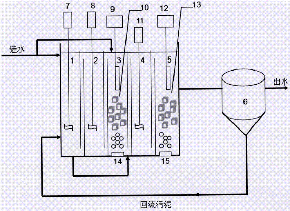
[0019] S1, press as figure 1 The shown structural assembly reaction device includes an integrated reactor and a sedimentation tank 6, and the integrated reactor is provided with an anaerobic reactor 1, the first anoxic reactor 2, the first aerobic reactor 3, and the second anaerobic reactor. Oxygen reactor 4 and the second aerobic reactor 5 are connected in sequence, agitators 7, 8, 11 are respectively arranged in the anaerobic reactor 1,...


PUM


Abstract

The invention discloses an energy-saving and consumption-reducing shortcut nitrification-denitrification phosphorus removal technology. An anaerobic reactor, a first anoxic reactor, a first aerobic reactor, a second anoxic reactor and a second aerobic reactor are sequentially connected with one another; activated sludge from a secondary sedimentation tank of a municipal sewage is inoculated to each reactor; a part of raw water enters the anaerobic reactor, and the other part of the raw water directly enters the first aerobic reactor through a water feed pump; and a part of an effluent of the anaerobic reactor directly enters the first anoxic reactor, and the other part of the effluent is shunted to the first aerobic reactor through a metering pump, wherein the DO of the first aerobic reactor is controlled to be 0.5-1.0mg/L, the pH value is controlled to be 8.0, and the DO of the second aerobic reactor is controlled to be 0.3-0.5mg/L. By adopting the energy-saving and consumption-reducing shortcut nitrification-denitrification phosphorus removal technology provided by the invention, under the normal-temperature low dissolved oxygen condition, stable accumulation of nitrite is realized and synchronously removal of phosphorus with denitrification is realized; and in the premise of ensuring the quality of the effluent, the sewage treatment efficiency is greatly improved.

Description

technical field [0001] The invention relates to the field of chemical industry, in particular to an energy-saving and consumption-reducing short-range nitrification and denitrification phosphorus removal process. Background technique [0002] Traditional anaerobic / anoxic / aerobic (A 2 / O) process is widely used in urban sewage treatment because of its good nitrogen and phosphorus removal effect. However, high operating costs and high energy consumption are still the main problems faced by urban sewage treatment plants. Therefore, research on new energy-saving and consumption-reducing A 2 / O process is of great significance for reducing the operating cost of sewage treatment plants. The basic principle of short-cut nitrification and denitrification biological nitrogen removal is to control the nitrification process in the nitrite stage and prevent NO 2 - further nitrification and then direct denitrification. The advantages of short-path nitrification and denitrification ...

Claims


Application Information

Patent Timeline
Patent Type & Authority Applications(China)
IPC IPC(8): C02F3/30C02F101/10
Inventor 吴春英谷风白鹭郭立秀魏薇
Owner JILIN INST OF CHEM TECH
Why Eureka
Try Eureka