Chamfering machine for wind turbine blade lining foam board

A technology for wind turbines and foam boards, which is applied in metal processing and other directions, can solve the problems of inability to adjust the chamfering angle and the amount of chamfering, not suitable for foam boards, and high labor intensity, and achieves good chamfering effect, simple structure, and high labor intensity. Adjustable effects

Pending Publication Date: 2017-11-17
山东盈九新能源科技有限公司
View PDF8 Cites 6 Cited by
  • Summary
  • Abstract
  • Description
  • Claims
  • Application Information

AI Technical Summary

Problems solved by technology

Manual processing is time-consuming and labor-intensive
[0005] Although there are chamfering machines with various structures, most of them are used for metal parts or rigid non-metallic parts, and the angle and amount of chamfering cannot be adjusted, so they are not suitable for soft and easy-folding foam boards.

Method used


Image

  • Chamfering machine for wind turbine blade lining foam board
  • Chamfering machine for wind turbine blade lining foam board
  • Chamfering machine for wind turbine blade lining foam board

Examples


Embodiment Construction

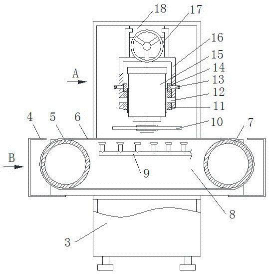
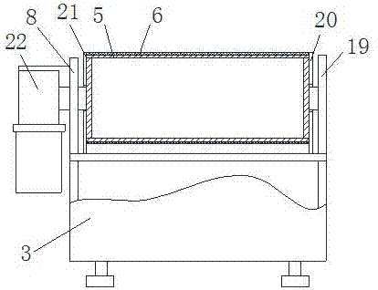
[0021] Such as figure 2 , image 3 with Figure 4 As shown, the chamfering machine for foam boards lining the wind turbine blades of the present invention includes a base, a conveying mechanism and a chamfering mechanism, both the conveying mechanism and the chamfering mechanism are installed on the base, and the conveying mechanism is in front of the chamfering mechanism. The base includes a chassis 3 and a front wall panel 19 and a rear wall panel 8 respectively arranged on the front and rear sides of the chassis 3 .

[0022] see figure 2 with image 3 , The conveying mechanism includes a driving roller 5, a driven roller 7, a conveyor belt 6 and a transmission device. The driving roller 5 and the driven roller 7 are installed on the left and right sides of the front wallboard 19 and the rear wallboard 8 respectively, and a conveyor belt 6 is connected between the driving roller 5 and the driven roller 7 . Shields 4 are provided on the bottom frame 3 on the left and r...


PUM


Abstract

The invention relates to a chamfering machine for a wind turbine blade lining foam board. The chamfering machine comprises a base, a conveying mechanism and a chamfering mechanism; the chamfering machine is characterized in that the conveying mechanism and the chamfering mechanism are installed on the base; the conveying mechanism comprises a driving roller, a driven roller, a conveying belt and a transmission device, the conveying belt is connected between the driving roller and the driven roller, one end of the driving roller is connected with the transmission device, and the transmission device is fixedly installed on the base; and the chamfering mechanism comprises a chamfering support, a guide rail, a chamfering support movement mechanism, a chamfering driving mechanism and a dip angle adjusting mechanism, the guide rail is installed at the upper portion of the base and is provided with the chamfering support movement mechanism, the chamfering support is installed on the guide rail and connected with the chamfering support movement mechanism, the chamfering driving mechanism is installed on the chamfering support and provided with a saw blade, and the chamfering support is further provided with the dip angle adjusting mechanism. The chamfering machine is simple in structure, chamfering cutting of the lining foam board is achieved, the structure is simple, the chamfering effect is good, efficiency is high, and adjustment is convenient.

Description

technical field [0001] The invention relates to a device used for chamfering a lining foam board pasted on the inner cavity wall of the blade during the production process of wind power generator blades, and belongs to the technical field of chamfering and splitting of lining foam boards. Background technique [0002] Blades are the most basic and critical components of wind turbines, which directly affect the conversion efficiency of wind energy. At present, the blades of wind turbines mainly include: ①Steel beam fiberglass skin blades, filled with foam plastic in the framework of section steel as longitudinal beam and steel plate as rib beam, and covered with FRP skin, generally used on large wind turbines; ②FRP The blade is wound with glass fiber and epoxy-coated on the surface of high-strength, light-weight, and aging-resistant glass fiber reinforced plastic (referred to as GFRP, a reinforced plastic made of epoxy resin, unsaturated resin and other plastics infiltrated i...

Claims


Application Information

Patent Timeline
IPC IPC(8): B26D1/18B26D7/01B26D7/06B26D3/00
CPCB26D1/18B26D3/00B26D7/01B26D7/0625
Inventor 张旭鹏陈刚
Owner 山东盈九新能源科技有限公司
Why Eureka
Try Eureka