Underwater blasting construction method for deep-water inclined bare rock foundation

A construction method and basic technology, applied in the direction of blasting, etc., can solve the problems of many drilling rigs, high requirements for base flatness, lack of innovation, etc., improve construction progress and economic benefits, overcome the effect of strong water flow, and reduce blasting The effect of stone volume

Active Publication Date: 2017-11-17
THE SECOND CONSTR OF CTCE GROUP +1
View PDF7 Cites 10 Cited by
  • Summary
  • Abstract
  • Description
  • Claims
  • Application Information

AI Technical Summary

Problems solved by technology

Underwater blasting of deep-water inclined bare rock foundations has the characteristics of fast water flow, large blasting volume, thick blasting depth, large number of drill holes, and high requirements for base flatness. Hole positioning, charge and plugging structure, and slag cleaning methods are difficult to meet the growing needs of underwater blasting construction of large deep water foundations
[0003] In the existing public technology, the underwater blasting construction method usually adopts the method of layered blasting, which emphasizes the theoretical calculation of blasting parameters, and reasonable blasting parameters can speed up the construction progress, but it is too simple and difficult to explain in the specific implementation method. Lack of new ideas, and vertical layered blasting for slag removal, large construction interference, ship positioning, drilling rigs, and low efficiency, seriously affecting the construction progress of a large amount of underwater blasting

Method used


Image

  • Underwater blasting construction method for deep-water inclined bare rock foundation
  • Underwater blasting construction method for deep-water inclined bare rock foundation
  • Underwater blasting construction method for deep-water inclined bare rock foundation

Examples


Embodiment Construction

[0030] The following will clearly and completely describe the technical solutions in the embodiments of the present invention with reference to the accompanying drawings in the embodiments of the present invention. Obviously, the described embodiments are only some, not all, embodiments of the present invention. Based on the embodiments of the present invention, all other embodiments obtained by persons of ordinary skill in the art without making creative efforts belong to the protection scope of the present invention.

[0031] An underwater blasting construction method for a deep-water inclined bare rock foundation provided by an embodiment of the present invention includes the following steps:

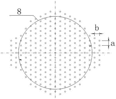
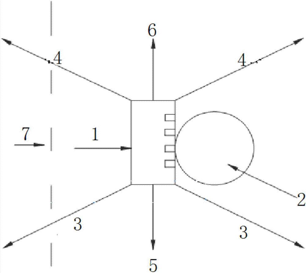
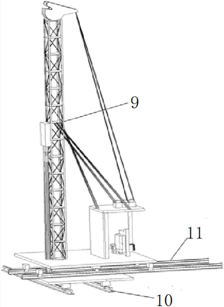
[0032] Underwater blasting is carried out by drilling and blasting ship 1 equipped with down-the-hole drilling rigs. The blasting sequence is from the lower part of the river bed to the higher part in sequence. There is no layering in the vertical direction. Depth 1-2.0m), drilling a...


PUM


Abstract

The invention discloses an underwater blasting construction method for a deep-water inclined bare rock foundation, and relates to the field of bridge deep-water foundation construction. The method comprises the following steps that before formal blasting, a depth measuring instrument is adopted and RTK-GPS is arranged to conduct plane and elevation three-dimensional scanning-measuring on an original river bed in a blasting area, and a reasonable blasting design is made according to foundation geological survey and three-dimensional scanning-measuring data; underwater blasting is constructed through a peripheral slope-making method, blasting is conducted in sequence from the low position to the high position of the river bed, vertical layering is avoided, drilling is conducted to the designed hole depth (including the over-drilling depth 1-2.0 m) each time, blasting is conducted once a day, and finally slag is removed at a time; and after a drilling-blasting ship is positioned through a six-cable positioning method, a casing is put downwards, underwater drilling is conducted through a down-hole drilling machine, a hole is filled with a processed explosive roll and blocked after the hole is cleaned, and blasting operation is carried out after blasting network connection. The method has the characteristics of fast positioning, low cost, less construction interference, rapid construction progress and the like, and is suitable for underwater blasting construction of the deep-water inclined bare rock foundation.

Description

technical field [0001] The invention relates to the field of deep-water foundation construction of bridges, in particular to an underwater blasting construction method of a deep-water inclined bare rock foundation. Background technique [0002] With the rapid development of bridge engineering, there are more and more river-crossing and sea-crossing bridges, and more and more underwater pier designs, especially on the Yangtze River and its tributaries, where the riverbed is mostly bare rock foundation, and it is inevitable to use underwater Blasting technology to achieve the conditions required for construction. The key technologies of underwater blasting and slag removal process include: blasting parameters, blasting network design research, positioning and anchoring measures for drilling and blasting ships under navigational conditions, rapid positioning of drilling holes, charging and blocking methods, blasting shock wave calculation, cleaning after blasting, etc. Slag an...

Claims


Application Information

Patent Timeline
Patent Type & Authority Applications(China)
IPC IPC(8): F42D3/04F42D1/00
CPCF42D1/00F42D3/04
Inventor 李勇海周新亚张少飞章好龙孙小猛胡晓东吴志鸿张勇方伏浪
Owner THE SECOND CONSTR OF CTCE GROUP
Why Eureka
Try Eureka