A Method of Couple Unbalance Identification Based on Gyro Flywheel Torque Coil Current

A technology of couple unbalance and torque coil, applied in the field of gyro flywheel couple unbalance identification, can solve the problems affecting gyro flywheel attitude measurement accuracy, low gyro flywheel torque output accuracy, torque coil torque noise, etc., so as to improve torque output accuracy and Attitude measurement accuracy, improving operation stability, and reducing the effect of one-fold frequency amplitude

Active Publication Date: 2020-06-16
HARBIN INST OF TECH
View PDF5 Cites 0 Cited by
  • Summary
  • Abstract
  • Description
  • Claims
  • Application Information

AI Technical Summary

Problems solved by technology

[0005] The purpose of the present invention is to solve the problem that when the existing gyro flywheel is in operation, the couple imbalance will cause the rotor of the gyro flywheel to tilt and vibrate, and the torque coil will generate torque noise, resulting in low precision of the torque output of the gyro flywheel and affecting the attitude measurement accuracy of the gyro flywheel. It will lead to system instability and even damage to components, and a method for identifying the couple unbalance based on the torque coil current of the gyro flywheel is proposed

Method used


Image

  • A Method of Couple Unbalance Identification Based on Gyro Flywheel Torque Coil Current
  • A Method of Couple Unbalance Identification Based on Gyro Flywheel Torque Coil Current
  • A Method of Couple Unbalance Identification Based on Gyro Flywheel Torque Coil Current

Examples


specific Embodiment approach 1

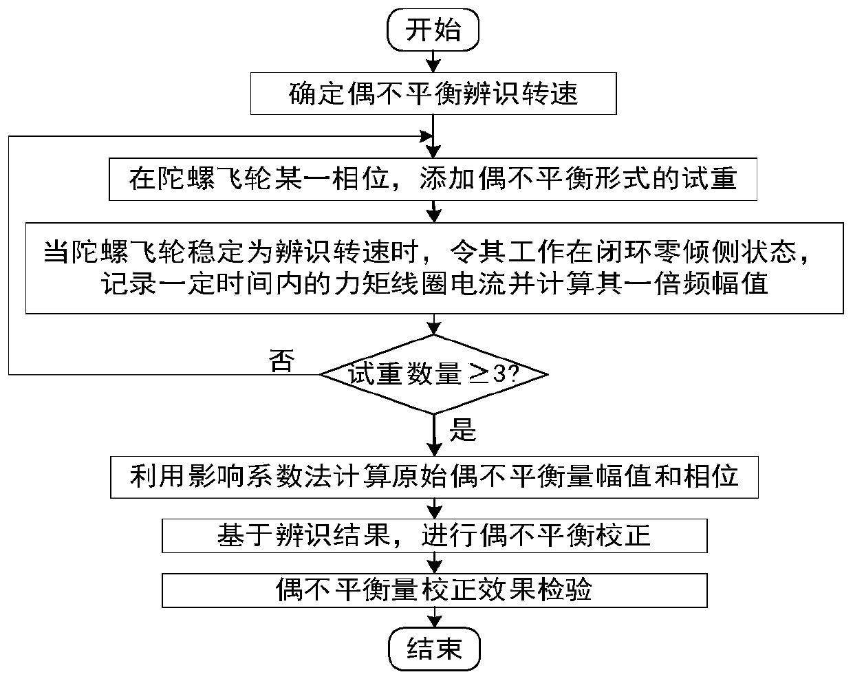
[0017] Specific implementation mode one: as figure 1 As shown, a method for identifying the couple unbalance based on the gyro flywheel torque coil current includes the following steps:

[0018] Step 1. Determining the identification speed of the couple unbalance;

[0019] Step 2. Identify the rotating speed according to the couple unbalance amount determined in step 1. Under different test weight conditions, perform torque coil current signal data acquisition and spectrum analysis to obtain the current signal spectrum analysis result; the different test weight conditions are different test weights Adding phases with different masses, adding phases with different mass for the same test weight or adding phases for different trial weights with the same mass;

[0020] Step 3, using the current signal spectrum analysis results obtained in step 2, based on the influence coefficient method, to identify the original couple unbalance of the gyro flywheel;

[0021] Step 4. According ...

specific Embodiment approach 2

[0023] Specific embodiment 2: The difference between this embodiment and specific embodiment 1 is that the specific process of determining the identification speed of the couple unbalance in the step 1 is as follows:

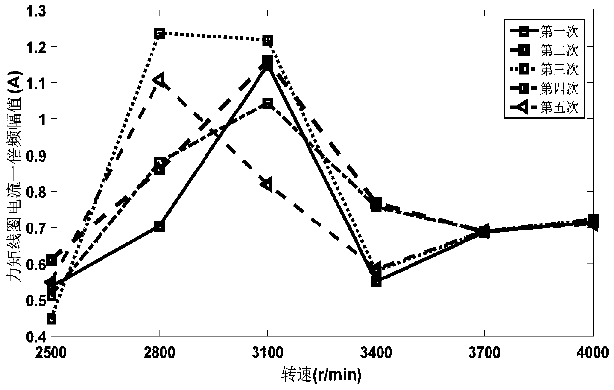
[0024] The repeatability of the double frequency of the torque coil current is used as the judgment standard;

[0025] Step 11, within the range of the gyro flywheel's working speed, select the test speed as ω i , i=1,2,...,n; the working speed range of the gyro flywheel is 2500r / min-4000r / min, and 300r / min is selected as the test speed interval, respectively 2500r / min, 2800r / min, 3100r / min, 3400r / min, 3700r / min, 4000r / min; n is a positive integer;

[0026] Step 12, when the test speed ω i After the operation is stable, make the gyro flywheel work in the closed-loop zero-tilt state (close-loop control is performed on the tilt angle of the gyro flywheel so that it does not tilt), and record the current of the torque coil within the time t (within 10 seconds); ...

specific Embodiment approach 3

[0031] Embodiment 3: The difference between this embodiment and Embodiment 1 or 2 is that in Step 2, according to the identification speed of the couple unbalance determined in Step 1, under different test weight conditions, the torque coil current signal data acquisition and Spectrum analysis, the specific process of obtaining the current signal spectrum analysis results is as follows:

[0032] Collect torque coil current and analyze it using FFT;

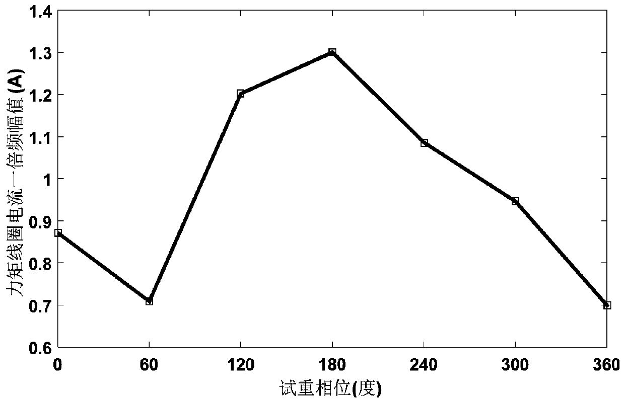
[0033] Step 21. In the gyro flywheel phase Add a trial weight in the form of a couple unbalanced, with mass m k ;

[0034] Step 22. When the gyro flywheel runs stably at the identification speed ω T , make the gyro flywheel work in the closed-loop zero-tilt state;

[0035] Step two and three, record the torque coil current signal within the time t;

[0036] Step 24: Use Fast Fourier Transform to calculate the torque coil current, and obtain the double frequency amplitude of the torque coil current corresponding to each test ...


PUM


Abstract

The invention relates to a gyro flywheel couple unbalance identification method, particularly to a couple unbalance identification method based on gyro flywheel moment coil current, and aims to solve the problems that during running of existing gyro flywheels, couple unbalance can cause flywheel rotor tilt vibration and moment coil moment noise, accordingly the gyro flywheel moment output accuracy is low, the gyro flywheel attitude measurement accuracy can be affected, and in a severe case, system instability or even component damage can be caused. The method includes: 1. determining couple unbalance identification rotation speed; 2. under different trial weight conditions, conducting moment coil current signal data acquisition and spectral analysis to obtain a current signal spectral analysis result; and 3. utilizing the current signal spectral analysis result obtained in step 2 to identify gyro flywheel original couple unbalance based on influence coefficient method; and 4. performing gyro flywheel couple unbalance correction according to the identification result obtained in step 3. The method provided by the invention can be applied to the rotor dynamic balancing technical field.

Description

technical field [0001] The invention relates to the technical field of rotor dynamic balance, in particular to a method for identifying the unbalanced quantity of a gyro flywheel couple. Background technique [0002] Micro spacecraft has the advantages of light weight, small size, low cost, short development cycle, easy technology update, high functional density, fast and flexible, and good mobility. Therefore, the development of kilograms to hundreds of kilograms can be quickly developed, produced and launched. The tiny spacecraft has become the main trend of the current aerospace technology development. Compared with existing spacecraft, tiny spacecraft have higher requirements in terms of volume, quality, cost, power consumption, function, and reliability. A system implementation technology that greatly increases the functional density of tiny spacecraft and greatly improves the working performance of tiny spacecraft. The attitude control system is an important subsyste...

Claims


Application Information

Patent Timeline
Patent Type & Authority Patents(China)
IPC IPC(8): G01C25/00
CPCG01C25/00
Inventor 霍鑫郑双朋刘海媛皮永江郭照升冯四兆彭继平
Owner HARBIN INST OF TECH
Why Eureka
Try Eureka