
Micro-nano optical detection device and micro-nano optical detection system

A light detection device and light intensity detection technology, applied in the field of optical detection, can solve the problems of not reaching the micro-nano size, single use, large modules, etc.

Pending Publication Date: 2017-11-17
LANZHOU UNIVERSITY
View PDF8 Cites 6 Cited by
  • Summary
  • Abstract
  • Description
  • Claims
  • Application Information

AI Technical Summary

Problems solved by technology

[0004] In view of this, the purpose of the embodiments of the present invention is to provide a micro-nano detection device to solve the problems of the prior art that the module is large, cannot reach the micro-nano size, and has a single use

Method used


Image

  • Micro-nano optical detection device and micro-nano optical detection system
  • Micro-nano optical detection device and micro-nano optical detection system
  • Micro-nano optical detection device and micro-nano optical detection system

Examples


no. 1 example

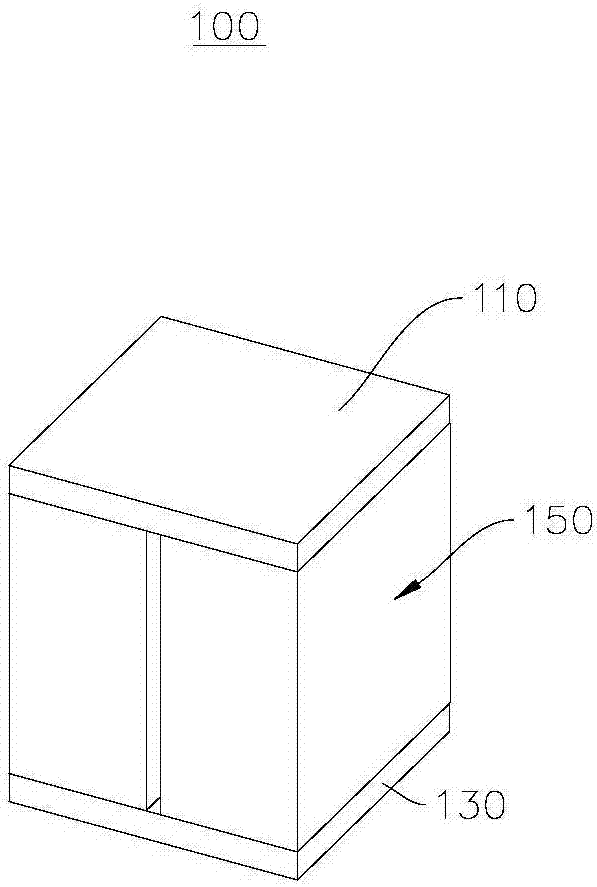
[0035] see figure 1 , figure 1 It shows a schematic diagram of a micro-nano photodetection device 100 provided by this embodiment.

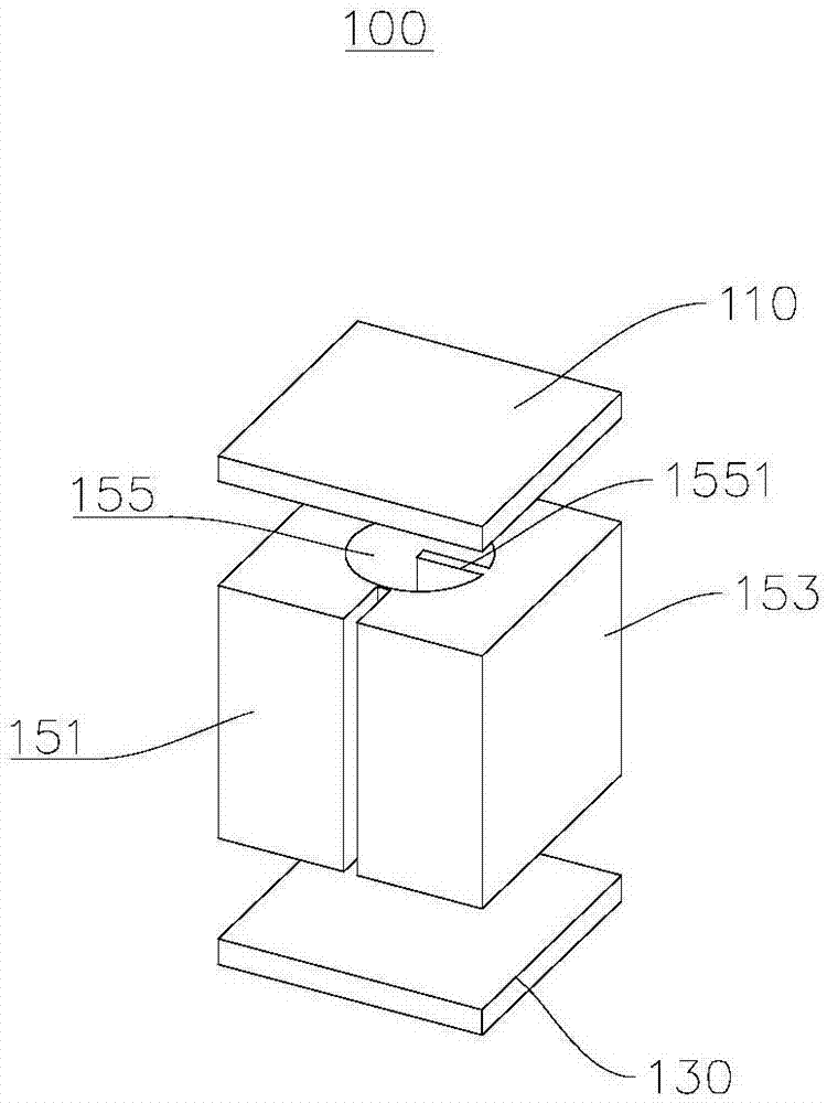
[0036] The micro-nano photodetection device 100 includes a first cover 110 , a second cover 130 and a conductive component 150 . see figure 2 , figure 2A schematic diagram of the assembly structure of the micro-nano photodetection device 100 provided in this embodiment is shown. Wherein, the first cover plate 110 and the second cover plate 130 are disposed opposite to each other, the first cover plate 110 is disposed above the conduction assembly 150, and the second cover plate 130 is disposed below the conduction assembly 150, Both the first cover plate 110 and the second cover plate 130 are in good contact with the conductive component 150 to prevent the electromagnetic wave (in this embodiment, the electromagnetic wave is light) transmitted through the conductive component 150 from leaking.

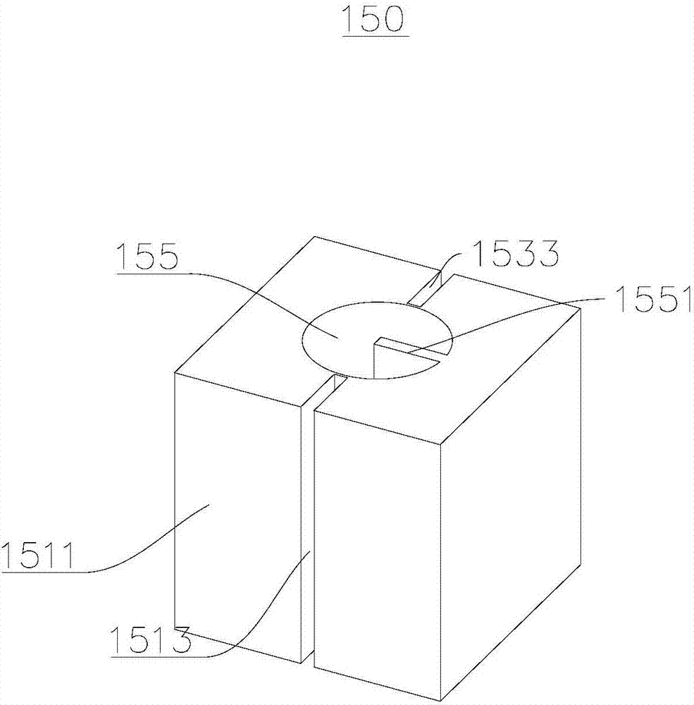
[0037] see image 3 , image 3 A first vie...

no. 2 example

[0055] This embodiment provides a light detection system 200, please refer to Figure 6 , Figure 6 A schematic diagram of the light detection system 200 provided in this embodiment is shown.

[0056] The light detection system 200 provided in this embodiment includes the micro-nano light detection device 100 and the spectrum analysis device 230 in the first embodiment. The spectrum analysis device 230 is disposed on one side of the second waveguide 153 of the micro-nano light detection device 100 , and is used for detecting and analyzing the spectrum of the light passing through the micro-nano light detection device 100 .

[0057] The micro-nano light detection device 100 in this embodiment is slightly different from the micro-nano light detection device 100 in the first embodiment, please refer to Figure 7 , Figure 7 A schematic diagram of the micro-nano photodetection device 100 provided in this embodiment is shown. Both the first cover plate 110 and the second cover ...


PUM

PropertyMeasurementUnit
radiusaaaaaaaaaa
radiusaaaaaaaaaa
thicknessaaaaaaaaaa

Abstract

The invention provides a micro-nano optical detection device and a micro-nano optical detection system and relates to the technical field of optical detection. The micro-nano optical detection device comprises a first cover plate, a second cover plate and a conduction assembly, wherein the conduction assembly is arranged between the first cover plate and the second cover plate; the first cover plate and the second cover plate are used for preventing electromagnetic waves conducted through the conduction assembly from being leaked; the conduction assembly comprises a first waveguide, a second waveguide and a resonant cavity; the first waveguide and the second waveguide are arranged at two opposite sides of the resonant cavity; the first waveguide, the resonant cavity and the second waveguide are used for conducting light with specific wavelengths. According to the micro-nano optical detection device provided by the embodiment of the invention, the light is coupled into the resonant cavity to generate Fano resonance or Lorentz resonance; light to be detected at a specific waveband is transmitted in a manner of coupling the light from one end of the first waveguide to one end of the second waveguide through the resonant cavity; whether the light with the specific wavelengths passes through the micro-nano optical detection device or not can be detected, so that a transmission condition of the specific wavelengths is detected.

Description

technical field [0001] The invention relates to the technical field of optical detection, in particular to a micro-nano light detection device and a light detection system. Background technique [0002] The equipment of the traditional spectrum detector is complicated, and it is not necessary to read the complete spectrum most of the time. The modules of the existing technology are relatively large, and the device size of the micro-nano scale cannot be reached, which seriously affects the integration and chip of the product. [0003] In many product inspections, many inspections do not need to read out complete spectral data, but only need to obtain specific wavelength data. Compared with the spectral detector for preparing the matching liquid, the preparation of the matching liquid is complicated and the utilization rate is not high. Using nanotechnology to prepare filters, although the precision is high, the chip scale still reaches the order of hundreds of microns. The ...

Claims


Application Information

Patent Timeline
Patent Type & Authority Applications(China)
IPC IPC(8): G01N21/41
CPCG01N21/41
Inventor 程琳周琪璋李絮
Owner LANZHOU UNIVERSITY
Learn More