Gate driving circuit with self-adaptive dead time

A gate drive circuit and dead time technology, applied in electrical components, output power conversion devices, etc., can solve problems such as increasing power loss, achieve high versatility, simple control methods, and avoid punch-through effects.

Inactive Publication Date: 2017-11-17
UNIV OF ELECTRONICS SCI & TECH OF CHINA
View PDF3 Cites 23 Cited by
  • Summary
  • Abstract
  • Description
  • Claims
  • Application Information

AI Technical Summary

Problems solved by technology

[0010] Although the traditional fixed dead time is relatively simple in design, in order to ensure that the upper and lower power tubes will not break through under all conditions, the dead time needs to be designed quite long, which will inevitably result in a long time body The diode conducts, increasing the power loss

Method used


Image

  • Gate driving circuit with self-adaptive dead time
  • Gate driving circuit with self-adaptive dead time
  • Gate driving circuit with self-adaptive dead time

Examples


Embodiment Construction

[0060] The present invention will be further described in detail below in conjunction with the accompanying drawings and specific embodiments.

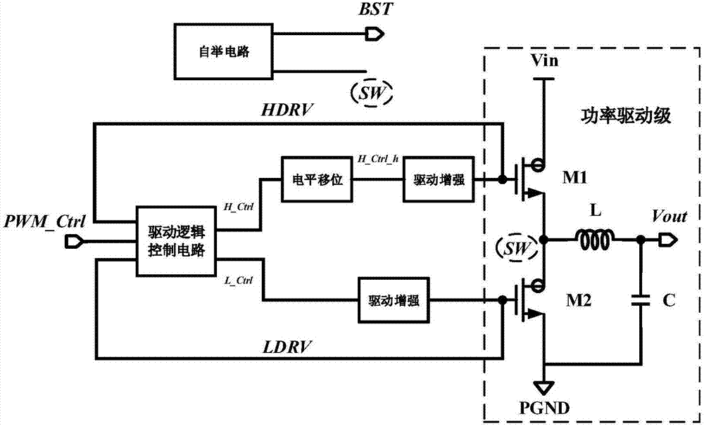
[0061] The gate drive circuit of the self-adaptive dead zone time proposed by the present invention, its principle block diagram is as follows figure 1 As shown, it is suitable for switching power supply circuits. The input signal of the driving logic control circuit is the pulse width modulation control signal PWM_Ctrl, and the control terminal signals are the high-end gate drive signal HDRV and the low-end gate drive signal LDRV; the pulse width modulation control signal The PWM_Ctrl and the high-side gate drive signal HDRV jointly control the turn-on and turn-off of the rectifier tube M2, and the pulse-width modulation control signal PWM_Ctrl and the low-side gate drive signal LDRV jointly control the turn-on and turn-off of the switch tube M1.

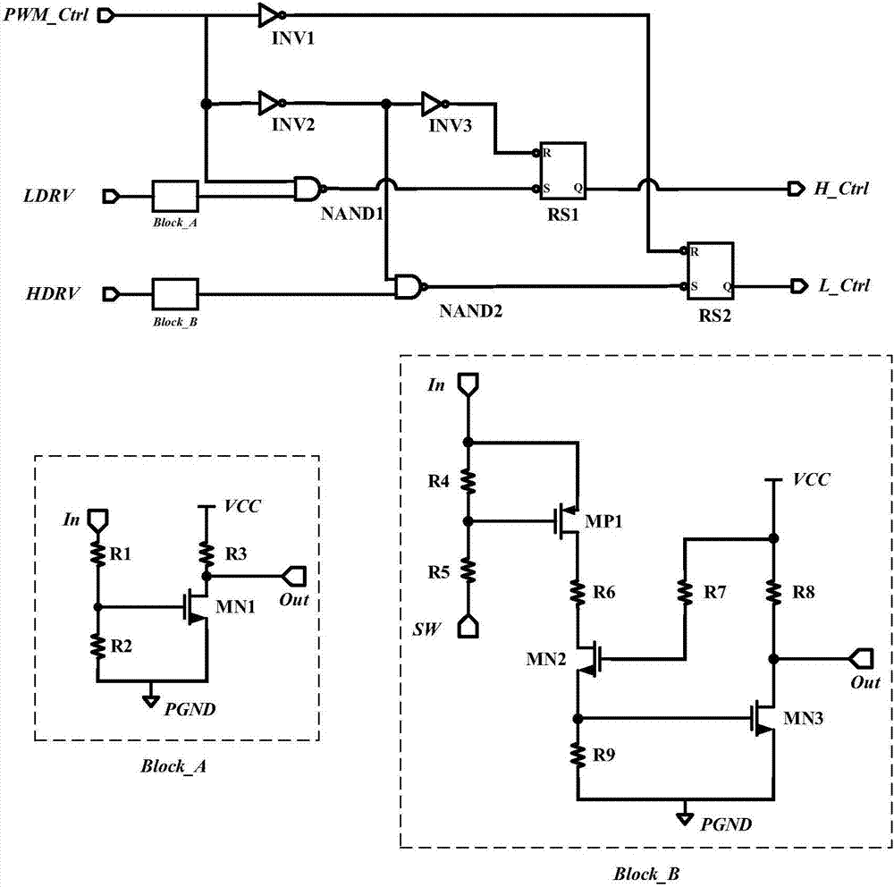
[0062] Specifically, as Figure 4 As shown, in the drive logic control circuit, when ...


PUM


Abstract

The invention, which belongs to the technical field of electronic circuits, provides a gate driving circuit with self-adaptive dead time, wherein the gate driving circuit is suitable for a switch power supply circuit. With control by a drive logic control circuit, crossed condition of high-end and low-end driving units is realized, so that the self-adaptive dead time function is realized. A level shift circuit enables a control signal generated by the drive logic control circuit to be lifted to a power rail with high-end driving; and a bootstrap circuit generates the power rail with high-end driving by means of a charge pump. A first driving enhancement circuit and a second driving enhancement circuit enhance drive control signals to be gate drive signals with ampere levels. A power drive stage of the switch power supply circuit is connected to a gate drive signal generated by a gate drive circuit and an output voltage Vout is generated. According to the invention, the dead time is adjusted adaptively based on the dimension of the power tube to avoid penetration; and the control way is simple and self-adaptive dead time control is realized with low costs; and the universality is high.

Description

technical field [0001] The invention belongs to the technical field of electronic circuits, and relates to a gate drive circuit with self-adaptive dead zone time. Background technique [0002] In the switching power supply circuit using synchronous rectification technology, in order to ensure that the upper and lower tubes are not turned on at the same time, so as to avoid damage to the circuit, it is necessary to set a dead time during the switching conversion process to protect the safe operation of the circuit. [0003] Such as figure 1 Shown is the gate drive circuit for the switching power supply circuit. The power driving stage in the switching power supply circuit includes a switching tube M1, a rectifying tube M2, an inductor L and a capacitor C. Both the switching tube M1 and the rectifying tube M2 are NMOS power tubes. The drain of the tube M1 is connected to the input voltage Vin, its source is connected to the drain of the rectifier tube M2 and connected to the ...

Claims


Application Information

Patent Timeline
Patent Type & Authority Applications(China)
IPC IPC(8): H02M1/38
CPCH02M1/38H02M1/385
Inventor 周泽坤袁东石跃李登维石旺张波
Owner UNIV OF ELECTRONICS SCI & TECH OF CHINA
Why Eureka
Try Eureka