Bolt sleeve of wind power blade, blade root embedded part and production method of wind power blade

A technology for wind power blades and bolt sleeves, which is applied in the direction of threaded fasteners, nuts, connecting components, etc., can solve the problems of poor bonding force and changes of bolt sleeves, and achieve good cold and heat shock resistance, wide adaptability of blades, The effect of meeting complex load requirements

Inactive Publication Date: 2017-11-21
SINOMATECH WIND POWER BLADE +1
View PDF7 Cites 5 Cited by
  • Summary
  • Abstract
  • Description
  • Claims
  • Application Information

AI Technical Summary

Problems solved by technology

However, the bonding force between the bolt sleeve and the blade root of the equal-diameter design is poor
[0003] At present, the bolt sleeves of wind turbine blades mainly transfer stress through glued connections, and the glued interface that transfers stress is easily affected by the operating environment and process conditions.

Method used


Image

  • Bolt sleeve of wind power blade, blade root embedded part and production method of wind power blade
  • Bolt sleeve of wind power blade, blade root embedded part and production method of wind power blade
  • Bolt sleeve of wind power blade, blade root embedded part and production method of wind power blade

Examples


no. 1 example

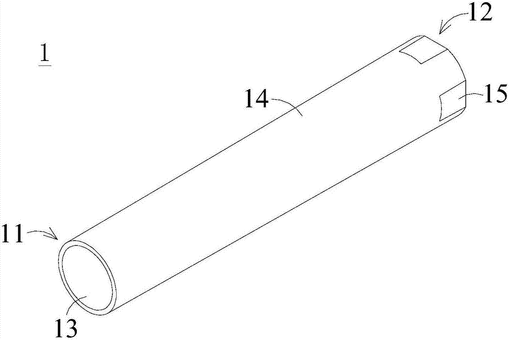
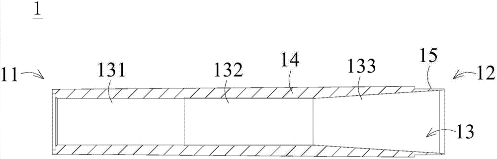
[0036] figure 1 It is a three-dimensional schematic diagram of the bolt sleeve structure of the wind turbine blade according to the first embodiment. figure 2 It is a schematic cross-sectional view of the bolt sleeve structure of the wind turbine blade according to the first embodiment.

[0037] As shown in the figure, the embodiment of the present invention provides a bolt sleeve 1 of a wind power blade, which can be pre-embedded in the blade root of the wind power blade, and a bolt rod can be screwed and fixed to the bolt sleeve 1, and then the bolt rod can be used to Connect with the outside. It can also be selected to be directly screwed and fixed with the external bolt shank. In order to use the bolt sleeve 1 to securely connect the wind turbine blade with the generating set.

[0038] In this exemplary embodiment, the bolt sleeve 1 can be cylindrical and long (the cylindrical shape is more suitable for lightweight design), and can include a first end 11 and a second e...

no. 2 example

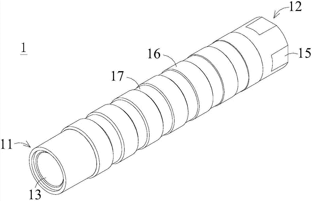
[0045] image 3 It is a three-dimensional schematic diagram of the bolt sleeve structure of the wind turbine blade according to the second embodiment. Figure 4 It is a schematic side view of the bolt sleeve structure of the wind turbine blade according to the second embodiment. Figure 5 It is a schematic cross-sectional view of the bolt sleeve structure of the wind turbine blade according to the second embodiment.

[0046] As shown in the figure, the bolt sleeve 1 of the second embodiment of the present invention can also be cylindrical and strip-shaped (cylindrical shape is more suitable for lightweight design), and can include a first end 11 and a second end 12 . The first end 11 is an end extending toward the root of the wind turbine blade, and the second end 12 is an end extending toward the tip of the wind turbine blade. The first end 11 can be exposed on the outer end surface of the blade root, the first end 11 can be selected to be flush with the end surface of the ...


PUM


Abstract

The invention discloses a bolt sleeve of a wind power blade, a blade root embedded part and a production method of the wind power blade. The bolt sleeve of the wind power blade is embedded into a blade root of the wind power blade. The bolt sleeve comprises a first end and a second end; the external diameter of the bolt sleeve is gradually reduced from the second end to the first end; the bolt sleeve is provided with an inner hole; the inner hole penetrates through the first end of the bolt sleeve, and stretches along the axis of the bolt sleeve; the inner hole comprises a front section, a middle section and an inner section; and internal threads are formed in the middle section of the inner hole. By adopting mechanical connection instead of gluing connection, the stability of the interfacial strength of a common bolt sleeve is improved, the overall weight of the blade root is reduced and the blade cost can be reduced advantageously.

Description

technical field [0001] The present invention generally relates to a production technology of wind power blades, in particular, relates to a bolt sleeve of a wind power blade, a blade root embedded part and a wind power blade with mechanical connection instead of glued connection, which improves the stability of the interface strength of the general bolt sleeve. Method of leaf production. Background technique [0002] In the production of wind power blades, generally multiple bolt sleeves are directly embedded in the root of the wind power blade as a whole, and the blade root can be selected to be integrally formed with the main body of the blade. However, due to the high strength requirements of the blade root of the composite material, the toughness is poor. Therefore, in the prior art, in order to avoid affecting the overall shape of the blade root after the bolt sleeve is pulled off, the shape of the bolt sleeve is generally selected as an equal-diameter design. However...

Claims


Application Information

Patent Timeline
Patent Type & Authority Applications(China)
IPC IPC(8): F16B37/04F03D80/00
CPCF16B37/04Y02P70/50
Inventor 高国强王战坚王鹏李权舟
Owner SINOMATECH WIND POWER BLADE
Why Eureka
Try Eureka